This thread has been locked.

If you have a related question, please click the "Ask a related question" button in the top right corner. The newly created question will be automatically linked to this question.

DRV8210: Excitation circuit for a fluxgate

Part Number: DRV8210
Other Parts Discussed in Thread: TLV3201, TLV9061,

Hello all,

We developed a circuit for a fluxgate current sensor using the DRV8210 as H-bridge driver, the TLV9061 for amplification and the TLV3201 comparator to control the phase input for DRV8210. Please see schematic:

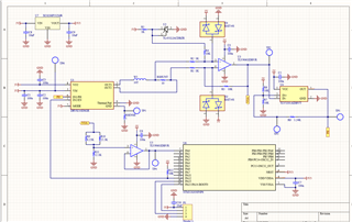
The DRV8210 drives the sensing coil W1, with 10 turns, and as soon as current on the coil reaches ~ 20mA the direction of drive is reversed. This is done by amplifiying the voltage drop across RSHUNT by 10 times and adding an 2.5V offset, then the hysteresis comparator made with TLV3201 reverses the phase input to DRV8210 as VOA get above 4.5V or drop below 0.5V. The rest of the circuit is for VOA range adjustment from 5V to 3.3V and signal evaluation with a MCU.

Is this circuit valid? We ran LTspice simulations and the results were good. However, I am worried about voltage spikes across RSHUNT, which might damage the op-amp, even thought there are diodes to both rails to protect it.

Also, we read in the datasheet that drive current can also be sensed with a resistor connected from the DRV8210 ground to board ground. However, we could not understand the explaination in the datasheet very well. Should the current through this current sense resistor (RSENSE) = Drive current + Quiscent current? If this is true, then can we directly use the voltage drop across this resistor as the input to the comparator, thus eliminating the amplifier in the control loop?

Any general advice on the circuit will be appreciated, too!

Zhi

  • Hi Zhi,

    The datasheet explains that the voltage drop across the SENSE resistor connected between IC GND and common GND should not exceed 0.5V. The reason is that all internal circuitry is reference to the IC GND. Adding too much offset to the IC GND will affect the operation of the IC. You need to size your resistor such that the current does not cause a voltage drop higher than 0.5V. Of course you need to take into account current spikes, inrush current, and possible OCP (overcurrent) from accidental OUT to GND or VM shorts. 

    Since 0.5V is the abs max voltage drop allowed on the GND pin, the voltage drop across the sense resistor during steady state will always be much lower than 0.5V. So an amplifier will most definitely be needed to ensure it is sufficient for the comparator input. if the voltage is too low, input offset error and other tolerances will impact the comparator output and lead to inaccurate results.

    Regards,

    Pablo Armet

  • Hello Pablo,

    Thank you for the explaination. I understand now. However since an amplifier is needed too, we will just stick to sensing current in-line.

    Best regards,

    Zhi

  • Hi Zhi,

    Understood. Let me know if you have any other questions.

    Regards,

    Pablo Armet