


Other Parts Discussed in Thread: CSD19532Q5B, DRV8353
The DRV8353Rx-EVM is a 100V-capable evaluation module that can be used to evaluate the functionality and features of the DRV8353Rx. The DRV8353Rx drives 6 CSD19532Q5B 100V power MOSFETs for the power stage. The MOSFETs have a low Qg of 48nC and a low Qgd of 8.7nC typical.
Why should I use a low IDRIVE setting when using the DRV8353Rx-EVM?
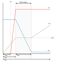
Due to the small value of the Qgd and Qg, it doesn’t take much gate current to switch the MOSFETs quickly. The MOSFET drain to source voltage (VDS) slews during the charging of the Cgd parasitic capacitance of the MOSFET (see image below), and since the Qgd of the FET is 8.7nC typical, this means that it takes very little amount of charge to charge up the Cgd capacitor and completely slew the VDS voltage.
In order to avoid slewing the VDS voltage too quickly for a low Qgd MOSFET, it is necessary to use a low IDRIVE setting. For the DRV8353Rx EVM, using the lowest IDRIVE setting of 50mA for IDRIVEP and 100mA for IDRIVEN is recommended to avoid switching the FETs too fast. Using the lowest IDRIVE setting of the DRV8353 will result in a VDS slew rate of approximately Qgd/IDRIVE = 8.7nC/50mA = 175ns rise time, which is still quite fast. For more information on selecting the proper IDRIVE setting, see the Understanding Smart Gate Drive App Note.
What are the issues with using a higher IDRIVE?
If a higher IDRIVE setting is used, this results in a faster VDS slew rate, which can result in voltage ringing, overshoot, and undershoot on SHx, GHx, and GLx during MOSFET switching. This ringing is due to the parasitic inductance of the PCB gate and source traces which can cause inductive spiking. If the voltage ringing is too large, it can result in a violation of the abs max pin ratings of the device which could lead to damage to the driver. Using the lowest IDRIVE settings helps to reduce the voltage ringing during switching to help the device operate below the abs max ratings of the device. Using the lowest IDRIVE setting also reduces EMI concerns as well.
When do I need to change my IDRIVE settings?
The default IDRIVE settings for the DRV8353 is 1A source and 2A sink, which means that any time the register settings are reset to the default values, the IDRIVE settings for the EVM will need to be reconfigured to the lowest IDRIVE settings. For more information on when the register settings are reset to the default values, please see this e2e FAQ.
How do I reconfigure my IDRIVE settings over SPI using the DRV8353Rx GUI for the EVM?
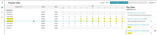
After enabling the system but before spinning the motor, go to the register map page of the GUI and change the Gate Drive HS and Gate Drive LS registers so that bits 0-6 are set to 0. This can also be done under the Field View by selecting 50mA for IDRIVEP and 100mA for IDRIVEN from the dropdown menu. This needs to be done for both the Gate Drive HS register and the Gate Drive LS register.
If the register write is changed from Immediate to Deferred, then the “Write All Registers” button will need to be pressed to write the register settings. It is always a good idea to read all registers to ensure that the desired register settings were properly written to.
