This thread has been locked.

If you have a related question, please click the "Ask a related question" button in the top right corner. The newly created question will be automatically linked to this question.

DRV8876: OUT1 supply shorted with a TVS diode

Part Number: DRV8876
Other Parts Discussed in Thread: DRV8714-Q1, DRV8718-Q1

Hello,

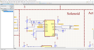
I am trying to figure out why the OUT1 supply of DRV8876 is getting shorted when used in the configuration as shown in the schematics below. There is a TVS diode at the output connected between OUT1 and OUT2 to suppress the back emf generated by a solenoid. After a few power up cycles the DRV8876 OUT1 is getting shorted some how.

Is this not a recommended set up with the TVS diode? I have tried using a standard diode in place of D4 whose cathode is connected to the OUT1 supply and the anode is connected to OUT2. It works fine in that configuration no failures so far.

Please have a look at the schematics and let me know your feedback.

Thanks,

  • Please have a look at the schematics and let me know your feedback.

    Hi,

    To know if the TVS is the root cause of problem, we need other condition such as VM voltage which you didn't provide.

    TVS diode at the output connected between OUT1 and OUT2 to suppress the back emf generated by a solenoid.

    Why do you need to suppress the back emf? The FETs already have the body diode to clamp the output within VM+0.9v.

    I have tried using a standard diode in place of D4 whose cathode is connected to the OUT1 supply and the anode is connected to OUT2.

    Again, lack of information. What is a standard diode? Let's assume it is a Schottky rectifier diode, then the diode will conduct as a freewheeling to circulate the inductive during solenoid turned off, which is a better design than using a TVS.

    Brian

  • Hi Brian,

    Thank you for the quick reply.

    The VM voltage used in this application is 12V. It is coming from a 12V lead acid battery so expect a voltage range of 11V to 14.5V.

    Why do you need to suppress the back emf?

    You know, the TVS suppressor here is actually used as a fly back diode. When the solenoid shaft moves up or down it generates a back emf which could be higher than the input voltage applied. The TVS diode used here has a breakdown voltage (Vbr) >31V. Which is suppose to suppress the reverse voltage.

    Thanks,

    Khan

  • You know, the TVS suppressor here is actually used as a fly back diode. When the solenoid shaft moves up or down it generates a back emf which could be higher than the input voltage applied. The TVS diode used here has a breakdown voltage (Vbr) >31V. Which is suppose to suppress the reverse voltage.

    Well, in this case with VM=12v, the TVS is useless as if the outputs is higher than VM+0.9V , say 15v, then the driver chip is toast as the TVS only conduct at 31v and higher.

    Again, the FET has the body diode and so no need to have external flyback diode unless you have a good reason to think the internal body diode is not enough.

    Brian

  • Well, in this case with VM=12v, the TVS is useless as if the outputs is higher than VM+0.9V , say 15v, then the driver chip is toast as the TVS only conduct at 31v and higher.

    Ok, when you said driver chip, do you mean the gate driver inside of DRV? do you recommend a method/circuit to protect the chip in case the output is higher than 15V?

    -Khan

  • Ok, when you said driver chip, do you mean the gate driver inside of DRV? do you recommend a method/circuit to protect the chip in case the output is higher than 15V?

    The driver chip is DVR8876.

    The block diagram shows the internal output FETs have the body diodes built in, and so the output cannot be high than VM or lower than GND more than 0.7v (0.7v is diode forward voltage).

    Again, no need to add protection between outputs.

    Brian

  • Hi Brain,
    The attached picture shows the waveform captured at the solenoid port. As you can see the output voltage is easily spiking to more than 150V for a couple of microseconds. This back EMF is seen not when the voltage is applied to the solenoid but rather when it is released. Also, this test is performed on solenoid output without a DRV chip in the loop.
    Knowing this output voltage, do you think the body diodes are sufficient? no external protection is necessary?
    Thanks,
    Khan
  • The attached picture shows the waveform captured at the solenoid port. As you can see the output voltage is easily spiking to more than 150V for a couple of microseconds. This back EMF is seen not when the voltage is applied to the solenoid but rather when it is released.

    Without the time per division on the waveform I can't tell how long the pulses are, and before and after the event the DC voltage levels are the same -- don't see when solenoid is turned off. Not a very meaningful waveform to be honest. 

    Of course the bemf noise would be total difference with the DVR connected and driving the solenoid.

    Brian

  • You may see the voltage per division is set to 50V and the time per division is 1us as there is on the top status bar in the picture.
    Since the voltage level is zoomed out to 50V/division you can't really see the actual DC voltage it is sitting at, it is sitting at 12V. The lump of voltage spikes you see in the picture are a result of voltage being released off of the solenoid.
    Can the body diode of the DRV8876 withstand 150V of voltage for 2us?
    -Khan
  • Hi Mahboob,

    Can the body diode of the DRV8876 withstand 150V of voltage for 2us?

    No it cannot.

    This app-note explains how to protect against BEMF overvoltage. The best solution is to braking the motor instead of costing to a stop. 

    How are you driving the outputs? Do you switch from Forward/Reverse driving to Brake or Coast? if Coast, the energy due to BEMF can flow back to VM though the body diodes causing the VM voltage to increase. When braking, the current is forced to recirculate between the two LS FETs and the solenoid. Therefore, no current pumps back to VM supply.

    Regards,

    Pablo Armet

  • The lump of voltage spikes you see in the picture are a result of voltage being released off of the solenoid.
    Can the body diode of the DRV8876 withstand 150V of voltage for 2us?

    The inductive current when interrupted would create the high 150v spikes, without any flywheel diode in connection. However, when the solenoid is driven by the DVR, the moment the current is turned off, the diode will conduct as soon as the spike voltage is higher than 0.7v and so you will not see such high voltage spikes. It will be fine.

    Brian

  • Hi Pablo,

    Thank you for the response. Your explanation make sense.

    We had programmed the micro-controller to forward drive the DRV8876 when it's time to turn on the solenoid and then pull the nsleep pin low when it's time to turn the solenoid off. 

    I had a look at the app-note you attached it says "the regulator powers up a minimal portion of the device while keeping the rest of the device in a low power mode. This provides a low power way for the gate driver to constantly monitor the voltage level of the analog power rail. If the analog power rail exceeds a voltage threshold the gate driver will automatically go into brake mode thus allowing the back EMF to safely dissipate".

    Given the above explain in the app-note, isn't that mean the DRV should work fine with the way we are driving it?

    BTW, thank you for the app-note it was informative.

    -Khan

  • Hi Mahboob,

    The portion of the app-note you attached is referring to the DRV8714-Q1 and DRV8718-Q1. This is a feature that those drivers have. The DRV8876 does not. The best control scheme is to switch the H-bridge to low-side recirculation ("Braking") to turn off the solenoid and after all the current has decayed, you can set nSLEEP=0V to bring DRV into sleep mode.

    Regards,

    Pablo Armet

  • Hi Pablo,

    The portion of the app-note you attached is referring to the DRV8714-Q1 and DRV8718-Q1. This is a feature that those drivers have. The DRV8876 does not.

    Man! I wish DRV8876 had that feature as well.

    There is a TVS diode at the output connected between OUT1 and OUT2 to suppress the back emf generated by a solenoid. After a few power up cycles the DRV8876 OUT1 is getting shorted some how.

    Going back to my original question. Do you have any insights on this one?

    Thanks,

  • Hi Mahboob,

    Going back to my original question. Do you have any insights on this one?

    Most likely the TVS diode abs max specifications was violated by the EMF. I suggest contacting the manufacturer of the TVS diode for support. 

    Regards,

    Pablo Armet