


Other Parts Discussed in Thread: DRV10987,
This is not a question. I just wanted to share the problems I had getting the MCF8316A working, some of them self-inflicted gunshot wounds, in case it will help anyone else. The boss pulled the plug once on this project. I was only able to get a second crack at it because the existing design with the DRV10987 is marginal for the current needed for this motor and we would get intermittent over current trips.
1. As stated in the errata, you cannot pole the chip registers while the motor is running. Do not click on any of those "Auto Read" buttons on the GUI. If the motor stops because of a fault, you can do a "Read All Registers" then to find out what caused the fault.
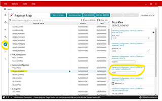
2. When you use the EVM GUI to write to the EEPROM of the chip, you can accidently change the i2c address, and then the chip won't respond on the expected 0x01 address, making you think you fried something. Go to the register map as shown below and make sure you have the i2c address set to what you want before you do a "Write to EEPROM".
3. The motor parameter extraction tool (MPET) runs automatically. This will cause unexpected behavior, like the motor starting, running for a few seconds, turning off, then trying to restart. Once you have a set of parameters to use, (either measured with the MPET or measured manually), and you want to avoid having the MPET run, make sure all the parameters in Figure 7-37 that need to be non zero are programmed in the EEPROM. (All the parameters that begin with MPET_ power up as zero and you don't need to worry about those.)

4. This may be an unusual problem, and was my own error, but the symptoms were very surprising. If you have too small a value capacitor for the charge pump, (47nF recommended), the charge pump will not reach the intended voltage. There is a charge pump under voltage lockout, which you might think would only cause the motor not to run. However, the first symptom I got was no i2c communication. The next thing I checked was the buck regulator output voltage, and that was only about 0.5V. This is because the charge pump powers the gate drivers for all the high side MOSFETs in the chip, including the one for the buck regulator.
I hope this helps someone else.
Dave Gustavson
