When determining the MOSFETs a gate driver can support one of the specifications that should be looked at is the maximum average gate current that the gate driver can supply. To switch a MOSFET gate drivers will supply a current to the gate of the MOSFET. When a MOSFET is switched many times a second this gate current will result in an overall lower average current that is required by the gate driver. The average current that will be required by the gate driver is determined by many factors, the main ones being the MOSFETS QG, the switching frequency of the MOSFETS, and the commutation method being used. The commutation method will determine the max number of MOSFETS that will be switched by the gate driver at once. For asynchronous trapezoidal commutation only one MOSFET will be switched at a time, whereas synchronous trapezoidal commutation will switch two MOSFETs at a time. Sinusoidal and FOC commutation both can require that all 6 of the MOSFETS in a motor system be switched.
External configurations and components can also affect the average gate current that will be required by the gate driver. External pulldown resistors between the gate and source of the MOSFET, like the RPD resistor in figure 1, will lead to an increase in power dissipation which will result in an increased load demand that is equal to the voltage at the gate divided by the pulldown resistor. This increased load will result in an extra load demand from the gate driver, to calculate the demand generated by this resistor simply use equation 1. Externally added capacitance, like QGD_EXT in Figure 1, will result in a greater total QG that will need to be charged by the gate driver when switching the MOSEFT. The amount of charge that will be added to the total QG of the MOSFET can be found using equation 2. In the case that parallel MOSFETs are used, the QG of each FET in parallel can be summed with the parallel MOSFETS being treated as a single MOSFET.
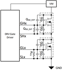
Figure 1: MOSFET Configuration
Equation 1: Resistor load = RPD * VGS * Duty Cycle
Equation 2: New QG = QGD+QGD_EXT + QGS_EXT + QGS
The average gate current that a gate driver can supply is limited mostly by the amount of current that the high and low side gate voltage regulators can supply before the regulator can no longer maintain its expected output voltage. These voltage regulators within the gate drivers are used to raise the gate voltage 10-12V above the voltage at the source of the external N-channel MOSFETs so that the MOSFETs can be turned on and held open. Depending on the architecture of the gate driver, the driver may have separate voltage regulators to drive the high side FETs and low side FETs or a single regulator for driving all external MOSFETs. If the device has a single regulator then the simplified equations for calculating the average gate current will be:
Asynchronous Trapezoidal: IAVG = QG * fPWM
Synchronous Trapezoidal: IAVG = 2 * QG * fPWM
Sinusoidal and FOC: IAVG = 6 * QG * fPWM
If the driver uses separate voltage regulators then the equations will be:
Trapezoidal: IAVG = QG * fPWM
Sinusoidal and FOC: IAVG = 3 * QG * fPWM
The architecture of a gate driver can be determined by looking within it’s datasheet. As an example, the DRV32x and DRV8329 gate drivers have different architectures with the DRV82x using separate voltage regulators for the high and low side gates and the DRV8329 using a single voltage regulator for both. After reading the datasheet the specifications for the average gate current capability for these devices can be found as shown below:
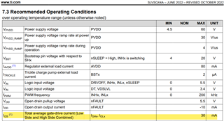
DRV832x - High and Low Separated Example:
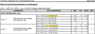
DRV8329 - High and Low together example: