


Dears,
I am placing this problem on behalf of our non-English speaking customer. Please take that in considerations, I am not a technical educated person :-) In below attached file there is table with registry numbers.
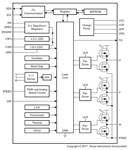
The additional information refers to the specification of the description of the values entered and read from the registers of the DRV10987SPWPR circuit. I need the clarification of this information to improve the control algorithm of the microprocessor that we use to control the speed of our three-phase synchronous motors.
In the EEPROM memory of the parameters of the chip DRV10987SPWPR (DRV10983PWPR), we upload the parameters in accordance with the manual. We have no problem with the description or setting and uploading values to the chip registers, everything is completely clear. Two parameters are key, namely the motor constant Kt and the phase resistance of the winding Rf. We determine the motor constant with an oscilloscope by measuring the course of the combined voltage when the measured motor is rotated to the rated speed, with an external motor (the measured motor works as an "idle" generator). We measure the Rf value with a four-point Ohmmeter for measuring small resistances.
Both values of these key parameters change to a certain extent during operation depending on the winding temperature and the motor load. However, the change of these values is within the tolerance resulting from the table of adjustable Kt and Rf values. The current value of the Kt parameter can be read from the work register (Reg. 0x03). However, it is not possible to determine the exact current value of the phase resistance of the motor winding directly. However, it can be calculated with some accuracy from other values read from the working registers of the chip.
The microprocessor of our control module reads from the work registers of the chip the values of the parameters that we want to use for the mathematical model of our motor so that we can optimize the control algorithm of the motor.
The current value of the motor constant Kt (Reg. 0x03) is read out. Kt value [mV/Hz] is calculated
The current value of the motor period T (Reg. 0x02) is read out. The Freq frequency [Hz] is calculated and then the revolutions [RPM] are calculated according to the number of pole-pairs of the specific motor.
Note: Is the calculation of revolutions based on the value in the register (Reg. 0x01) less accurate for some reason? Why.
The current value of the supply voltage register "SupplyVoltage" (Reg. 0x05) is read out. For the purpose of this document, I choose the abbreviation Upwr. Subsequently, the corresponding value of the supply voltage Upwr [V] is calculated.
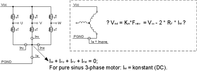
The current value of the motor current register "Motor Current" is read out, for the purposes of the document I denote it as Ix (Reg. 0x04). The corresponding current value Ix [A] is calculated.
However, here I have a problem with which current is being measured. In my opinion, it is not a DC power supply. Could it be the recalculated current according to the value of the register (Reg. 0x06) (parameter "spdCmdBuffer") or is it the current passing through the currently closed (bottom) transistor of the three-phase switching bridge? The value of the current and the place where it is measured are important to me for the correct determination of the voltage drop on the winding resistance. In principle (with considerable simplification) the engine speed or the frequency of the AC voltage on the motor is given by the equation:
Frekv = 1/Kt * ((Upwr*spdCmdBuff)/255 – Rf * Xx * Ix) (A)
The value of the phase resistance Rf is given by measurement, but is affected by the winding temperature. However, its correction could be calculated from the above equation according to the values of the individual parameters in the stable previous state. Subsequently, I would be able to calculate, relatively accurately, by how much the value of the register (Reg. 0x06( ("spdCmdBuff") needs to be changed), i.e. subsequently calculate the new value written to the speed control register (Reg. 0x30)
It would be possible to get accurate information about the current measurement. (including the moment of measurement, if it is not a constant value).?
It is a correct assumption that the equation holds:
Ix = (Ipwr * 255) / „spdCmdBuff“ (B)
- Where: Ix is the motor current according to the register (Reg. 0x04); Ipwr is the current from the supply voltage source
- If equation (B) holds, what is the relationship between the value of Rf and Xx in equation (A). In my opinion, Xx should just be a constant, but I'm not sure about its value, because it could be affected by the value of the load angle (that is, the phase shift between the phase voltage and the phase current), which is one of the parameters that are recorded in the registers of the DRV10987SPWPR chip ?
- If it would be difficult to answer the above-mentioned questions, it would be possible to obtain from Texas Instruments an algorithm according to which the values in the work registers are worked with, or directly an equation expressing the relationship between the work frequency and the measured parameters in the registers of the DRV10987SPWPR chip:
Frekv = FUNKCE (Kt; Rf; Upwr; Ix; spdCmdBuff) (A2)
Doplnkove_informace_DRV10987SPWPR (003).docx


 <-Thoughts