This thread has been locked.

If you have a related question, please click the "Ask a related question" button in the top right corner. The newly created question will be automatically linked to this question.

DRV8316: motor spin issue

Part Number: DRV8316

Hi team,

When the current loop is open (i.e. no position loop), the current sets a starting value and increases the electrical angle at a constant speed. Normally, the magnetic field is rotating at average speed and drives the motor to spin at a constant speed. However, the motor is running fast and slow, and it does not spin smoothly.

With the drive chip set to 3x mode and the slew rate modified to 200 V/µs, the motor spin is improved, but the above issue still persists. So the customer would like to know is there any way to improve it?  Thanks.

Best Regards,

Cherry

  • Hi Cherry, 

    Today is a US holiday, so many of our team members are out of office currently, returning later this week - please anticipate a delayed response 

    Best Regards, 
    Andrew 

  • Hi Cherry,

    Thank you for the question. Is this on one of TI's EVMs or it is on the customer's own board? Is this using trapezoidal commutation or FOC? Would the customer be able to send us waveforms for GLx, GHx, INHx, and INLx when they see the error? 

    Best,

    Eli

  • Hi Eli,

    Thank you for the support.

    Is this on one of TI's EVMs or it is on the customer's own board?

    It's custom board.

    Is this using trapezoidal commutation or FOC?

    FOC.

    Under normal, constant-speed magnetic fields, the motor should be driven to spin at a constant speed. 

    And only Control_Register_2 Register and Control_Register_5 Register are configured in registers, Control_Register_2 is set to 0x3D and Control_Register_5 is set to 0x02.

    Thanks and regards,

    Cherry

  • Hi Cherry,

    Thank you for the clarification. Would the customer be able to send us waveforms for GLx, GHx, INHx, and INLx waveforms? I would like to see if this is an issue with their commutation. The gate driver is not reporting any faults, correct? Also, is the customer is operating within the recommended ratings for the device found on page 6 of DRV8316 Three-Phase Integrated FET Motor Driver datasheet (Rev. B) (ti.com)?

    Best,

    Eli

  • Hi Eli,

    3x mode is selected, the input PWM wave is as follows: 

    (FPGA-emulated)

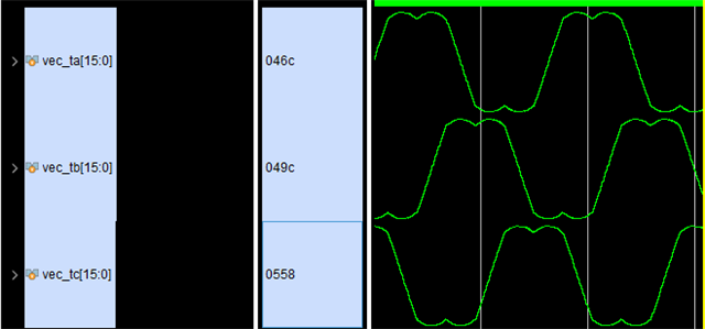
    The duty cycle of the three-phase PWM is as follows:

    (FPGA-emulated)

    Thanks and regards,

    Cherry

  • Hi Cherry,

    Thank you for the update. Are there any low-pass filters being used on the SOx pins? HF noise can affect current calculations, ensure SOx is sampled after CSA settling time, tSET.

    I would suggest obtaining the customers motor parameters. FOC estimates some of the motor's parameters (inductance, resistance, etc..) but what we have experienced previously if they are very low inductance motors then the algorithm will not estimate these values correctly and the motor will stutter as it spins. Perhaps this could apply to other motor parameters that the software cannot estimate properly.

    Best,

    Eli

  • Hi Eli,

    The customer does not have closed loop control of the current.

    The SVPWM is calculated and given directly from the electrical angle. The electrical angle is an artificial accumulation of constant velocity, normally the magnetic field should change at a constant speed and the motor should spin at a constant speed. But now the motor does not spin at a constant speed. 

    Thanks and regards,

    Cherry

  • Hi Cherry,

    I'll align with the team on this and get back to you by Friday.

    Best,

    Eli

  • Hi Cherry,

    Thank you for your patience. I will require some more information in order to debug this further.

    I would suggest obtaining the customers motor parameters. FOC estimates some of the motor's parameters (inductance, resistance, etc..)

    Can the customer provide these parameters or say which motor they are using?

    Would the customer be able to send us waveforms for GLx, GHx, INHx, and INLx waveforms? I would like to see if this is an issue with their commutation

    I will still need to see labeled waveforms for INHx and INLx. Unfortunately, just seeing the PWM does not give me enough information. Additionally, I have a few other questions. Do any faults occur? What voltage are you operating at? What IDRIVE setting are you using? What is the customer's deadtime?

    Best,

    Eli

  • Hi Eli,

    3x mode is used. In this mode, INLx is all connected to AVDD. INHx is followed by PWM wave. In this mode, PWM has no dead zone. FOC control uses a PMSM whose back electromotive force is a sine wave. There will be no failure. The working voltage is 28V.

    Regards,

    Annie

  • Hi Annie

    Thank you for the reply. To clarify, since the driver is in 3x PWM mode I will need an image containing waveforms for INHA, INHB, and INHC. These should not be FPGA emulated. I will need oscilloscope readings because this will allow us to determine any faults in the design. I still need the motor parameters as well. Has the customer tested if this problem occurs when using a DRV8316 EVM to drive the motor? That will show us if there is a potential issue with how the DRV interacts with this motor. Could the customer also provide waveforms for OUTA, OUTB, and OUTC? The reason I am requesting so many waveforms is to determine how the driver is outputting information and if there are any issues how INHx is receiving inputs. I appreciate the customer's willingness to provide information thus far!

    Best,

    Eli

  • Hi Annie,

    Please let me know if this issue was solved by resolving this thread. We believe there may have been some issue with the communication between the MCU and the driver but can only figure this out if the above waveforms are sent. I am marking this thread as closed on my end due to inactivity.

    Best,

    Eli