This thread has been locked.

If you have a related question, please click the "
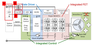
Ask a related question" button in the top right corner. The newly created question will be automatically linked to this question.

BLDC motor drivers architecture

Hi,
Below is my problem:
1.Label 1 in the picture, under what circumstances will an external LDO be used.
2.What is the Mosfet in the label 2 in the picture used for?
3.What does the "cut off" in the picture mean?
4.Can BLDC be single-speed closed-loop control? and give some reasons.
Thank you.

  • Hi Yunsheng,

    The diagram is an example of how a motor driver system is usually built. The supply voltage in this system is usually higher voltage (>12V) than the power supply for chips, which run off of 5V or 3.3V logic. So,

    1. An external LDO will be used because the system control (a microcontroller) only accepts 5V or 3.3V as its power supply. However, some BLDC devices have the feature where a 3.3V LDO is built in, so you could use that to power the controller, assuming you checked that the controller does not need more current than the device can provide through its LDO.

    2. and 3. are both part of the reverse polarity protection, meaning if you connect the supply backwards, the MOSFET will turn off (be cut off), protecting the system.

    4. BLDC can achieve constant speed in closed loop if the control system is built for it. Normally, you would have to program this algorithm, but in our integrated control devices, MCx83xx, enabling the speed loop is an option to keep the motor spinning at a constant speed.

    Regards,

    Hong

  • Thank you so much.

  • Hi Yunsheng,

    Great! Glad that I could help, and if you have any more BLDC driver questions, create another thread.

    Best,

    Hong