This thread has been locked.

If you have a related question, please click the "Ask a related question" button in the top right corner. The newly created question will be automatically linked to this question.

DRV8424: Unstable period of current regulation in full step

Part Number: DRV8424
Other Parts Discussed in Thread: DRV8711,

Hi support team.

Our customer asked us regarding unstable period of current regulation in full step.

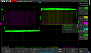
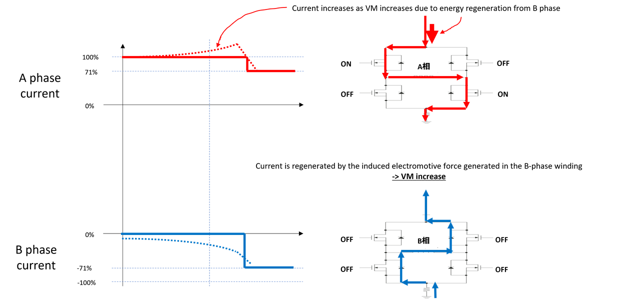
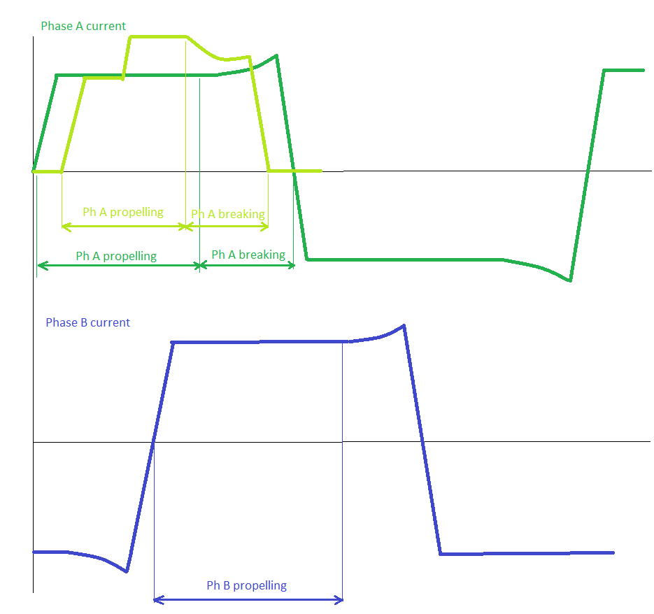
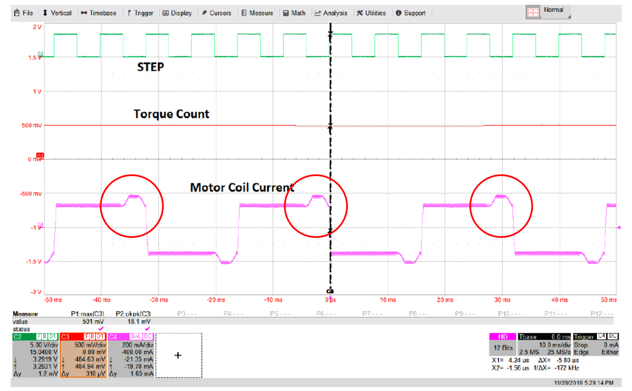
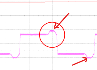
As shown in the waveform below during full step, an event in which the current waveform is distorted (worsened current regulation?) is observed just before the phase switching.
This is noticeable in STRC mode.
Why is this?
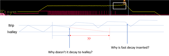
In theory, we thought that the regulation would not deteriorate because there should be no limit of OFF in one cycle in STRC.

Best regards,

Higa

  • Higa-san,

    Can you please also plot the PWM and measure the time period of this excursion?  If we can see what the outputs are doing, it will help with the explanation.

    Is this on an EVM or customer board?  

    Regards,

    Ryan

  • Ryan-san

    I will let me check to my customer.

    This is on the customer board.

    Best regards,

    Higa

  • Ryan-san

    I got the waveform data from my customer..

    Please refer to the attached file.

    Waveform data.zip

    Best regards,

    Higa

  • Higa-san,

    The waveform you provided is normal behavior for full-step mode in STRC decay mode. This is because STRC switched to slow decay and the current does not decay fast enough to the ITRIP level. This can be completed eliminated in STDD decay mode (dynamic decay) as this will use the required decay for current regulation.

    Note the slight distortion in STRC mode does not affect the functionality and can be used with no reliability issues. As a matter of fact this can provide slightly higher torque output compared to a clean square wave. No concerns with this. Thanks.  

    Regards, Murugavel

  • Hi Murugavel-san

    Thank you for answering.

    My understanding is that there isn't the limit of toff period on STRC mode in datasheet, is it correct?
    If incorrect, what is maximum toff?

    Best regards,

    Higa

  • Hey Daisuke-san,

    Correct, there isn't a limit of Toff period, but effectively Toff becomes the time between ITRIP and IVALLEY.  So there isn't a hard number limit.  

    Per 7.3.6.5 Smart tune Ripple Control,

    When the current level reaches ITRIP, instead of entering slow decay until the tOFF time expires, the driver enters slow decay until IVALLEY is reached. Slow decay operates similar to mode 1 in which both low-side MOSFETs are turned on allowing the current to recirculate. In this mode, tOFF varies depending on the current level and operating conditions.

    Regards,

    Jacob

  • Hi Jacob-san

    Thank you for answering.

    Regarding the customer data, does the Ivalley value change at the part where the current regulation deteriorates at the end of the step?
    Also, it seems to be fast decay instead of slow decay.
    Why is this?

    Best regards,

    Higa

  • Hey Higa,

    The off-time and thus the Ivalley time is dependent on the current in the winding. 

    This occurs on a step change between two micro-stepping levels when current is falling.  Fast decay is introduced to ensure current waveform does not get distorted and can "catch up" with the high speed STEP pulses. (See this E2E thread)

    This Thread also has a great description of Smart Tune Ripple Control:  DRV8256: How to chose TOFF pin setting

    Regards,

    Jacob

  • Hi jacob-san

    Thank you for your reply.

    Unfortunately your answer doesn't answer my question.
    I think my question was wrong, so I'll ask it again.

    Below is what my customers want to know.

    ・I would like to know the reason why the current rises within the same step.

    ・In the same step, Itrip and Ivalley are constant (that is, the ripple is constant), right? Is it wrong?
    The actual waveform is not attenuated up to Ivalley.

    ・You said that fast decay only occurs at the timing of step switching, but it seems that fast decay is inserted within the same step.
    Doesn't the device go into Fast decay when Itrip is greatly exceeded?

    The question is supplemented by the diagram below.

    Best regards,

    Higa

  • Hi Daisuke-san,

    I will try to help, though my experience is mainly based on DRV8711 and much older driver that has only slow decay mode.

    "I would like to know the reason why the current rises within the same step." - that current rise happens in winding when current falls in microstep mode or at the end of full step wave. At that moment this winding is breaking rotor trying to stop its movement caused by current rise (or direction change in full step) in other winding. So, first the rotor is being propelled by current change in one winding (or both windings) and then is being stopped by one winding. The winding with current bump works similar to shock-absorber, the more current rises the harder it is and behaves more like a spring (during slow decay). If current is constant or falls then that shock absorber becomes more soft (less vibrations) but to keep current constant or falling fast decay mode is needed.

    Now, why fast decay is needed. As I said before the winding experiencing current bump is breaking the rotor (direction of rotor movement is opposite to torque caused by that winding) at that moment so energy is flowing from that winding into h-bridge. To keep current constant or falling we need to take energy from that winding. During slow decay an energy is being lost mainly in winding and Mosfets resistances, lost power equals to I^2 x (Rwinding + 2 x Rdson). Fast decay is much more efficient because we additionally take energy from h-bridge with power equal to I x Vm.

    In case of current regulation algorithm in DRV8424 STRC mode, I guess datasheet explains it only in some simplified way.

    If I wanted to limit that bump I would try to lower Current Ripple Settings - Table 7-8, use other decay modes or use microstepping instead of full/half step modes.

    All above is just my opinion and I might be wrong though I think that energy flow can explain lots of phenomenons in stepper motor control.

    If your customer is concerned the current bump is causing some problems, maybe there is a way to solve them.

    PS. In case of falling current in microstepping mode energy of magnetic field that tries to keep current constant plays also a role and it may be the major one or it can only increase the breaking phenomena results.

    Best Regards,

    Grzegorz

  • Hey Daisuke-san,

    I checked with the design team and confirmed that smart tune ripple control (STRC) only uses Slow Decay, but if the current increases above a certain percentage level of ITRIP then Fast Decay is used.  I believe that is what you're seeing in your drawn diagram.  

    Grzegorz put a good detailed analysis above.

    Is there any actual problem you're seeing due to this device behavior, such as vibration or noise?  And has the customer tried Smart Tune Dynamic Decay (STDD) mode?  

    Regards,

    Jacob

  • Hello Daisuke-san,

    Please let me add to this further. Note the below screen capture. This was done with STRC and lowest ripple settings which also happen to be the single fixed setting in the DRV8424, which is 19mA + 1% of Itrip. The STRC normally uses slow-decay for current decay as much as possible. However when the output current rises above a certain threshold above Itrip set internally in the device (fixed percentage) it uses fast-decay and tries to bring down the rising current level to Itrip. In STRC TOFF is a function of the back EMF of the motor. When the back EMF is higher (as the motor spins faster) the TOFF becomes longer and longer. The yellow trace is OUT1 and pink trace is OUT2. The green trace is the OUTA phase current. Note the yellow trace wider and wider and when the back EMF exceeds certain value the TOFF is no longer seen. The output becomes a ON only situation from that point and once the current exceeds the internal threshold fast-decay kicks in (note the pink trace at this moment showing the opposite polarity conduction) and starts regulating at that higher threshold which is Itrip + 10%. Because this value is higher than Itrip the OUT1 remains ON throughout. This is seen as a bump.  

        . 

    This happens when the motor is free running with no load. When the motor is loaded the phase angle of the back EMF is shifted until the reserve torque is zero just before stalling. During this condition this bump will not be visible because the TOFF range in STRC slow-decay will be sufficient to regulate the current between Itrip and Ivalley. Please see below screen capture from motor spinning in such condition still in STRC, full-step.

    The STRC mode uses this phenomena to detect a stall by computing the backEMF to current phase difference as a torque count value. See this application note about stall detection, https://www.ti.com/lit/an/slvaei3/slvaei3.pdf.

    The bump does not cause any issues with motor operation in STRC. However if the customer does not want this they can use STDD decay mode or one of the Mixed decay modes. I'd recommend using the STRC for lowest ripple of the output current. When the motor runs under sufficient load this bump should minimize or disappear. I hope these details help you understand the cause for this behavior. This is expected behavior like I mentioned before.

    Regards, Murugavel  

  • Hi Pelikan-san and everybody

    Thank you for your kind explanation.

    Your explanation is very difficult for me, but what I understand is expressed in the diagram below.

    Is my understanding correct?

    Please let me know if anything is missing.

    Best regards,

    Higa

  • Hi murugavel-san

    Thank you for your kind explanation.

    I understand well.

    Thanks.

    Best regards,

    Higa

  • Hi Jacob-san

    Thank you for your explanation.

    Best regards,

    Higa

  • Hi Higa-san,

    Top (red) - waveform/diagram. The bump can also appear in this place, energy from regeneration from phase B is causing a bump because only slow decay is used or not enough of fast decay. Red diagram shows driving phase not a slow decay.

    Bottom (blue) - waveform/diagram. Diagram shows asynchronous fast decay, yes, regeneration can cause VM increase if VM bus is not loaded enough by other load like the second h-bridge at the same time. Current shape with dotted line does not seem to be correct, at least for a situation described by earlier waveforms. 

    Lets focus on situation when waveforms look like the ones that you sent before.

    I have drawn waveforms for full step mode, but I also included similar in half-step mode for half period.

    When phase is propelling motor rotor using only slow decay alone can provide us good current regulation. If phase is breaking motor rotor (additionally we need to also decrease often current that is being sustained by magnetic field) using slow decay alone or not enough of fast decay is causing a bump or current is falling slower than it is supposed to. 

    The above waveforms are only valid for the situation that you described earlier. Changing motor speed, VM voltage, decay mode, motor loading (described by Murugavel earlier) can change current bump shape, its position, it can disappear completely. 

    I was trying to described the cause of current bump from stepper motor side. 

    Murugavel has explained the phenomenon very well from driver side.

    PS. Phase B of my current waveform seems to be shifted by 180 deg. to table 7.4 (DRV8424), it would only change motor direction.

    Best Regards,

    Grzegorz

  • Hi,

    My explanation was very specific to STRC decay mode. While this mode has slow decay for most part it does switch to fast decay when the current in the winding exceeds 10% of the Itrip value. The DRV8711 does not have STRC decay mode and only supports previous generation decay modes. If slow decay was selected in the DRV8711 its behavior would be different. The bump shown in the original post was very specific to STRC decay mode which is definitely due to back EMF of the motor. Thanks.

    Regards, Murugavel 

  • Hi Pelikan-san Murugavel-san

    Thank you for your kind support.

    I understood well.

    I appreciate your support!

    Regards,

    Higa