This thread has been locked.

If you have a related question, please click the "Ask a related question" button in the top right corner. The newly created question will be automatically linked to this question.

MCT8316Z: motor driver Halt output pwm on phase shift

Part Number: MCT8316Z

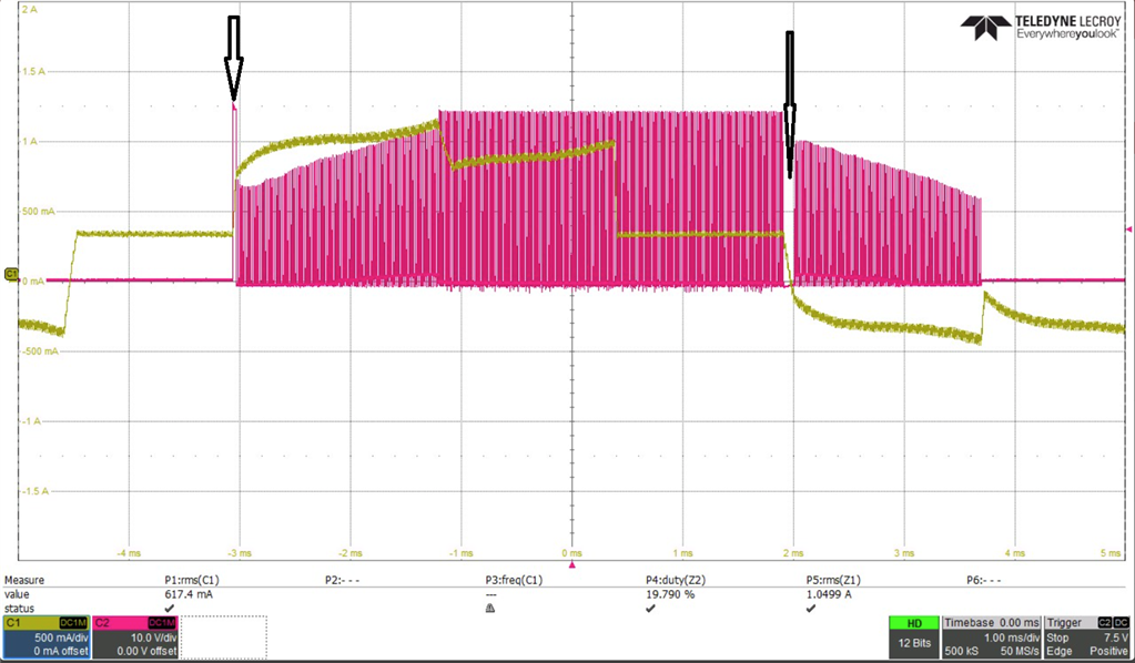
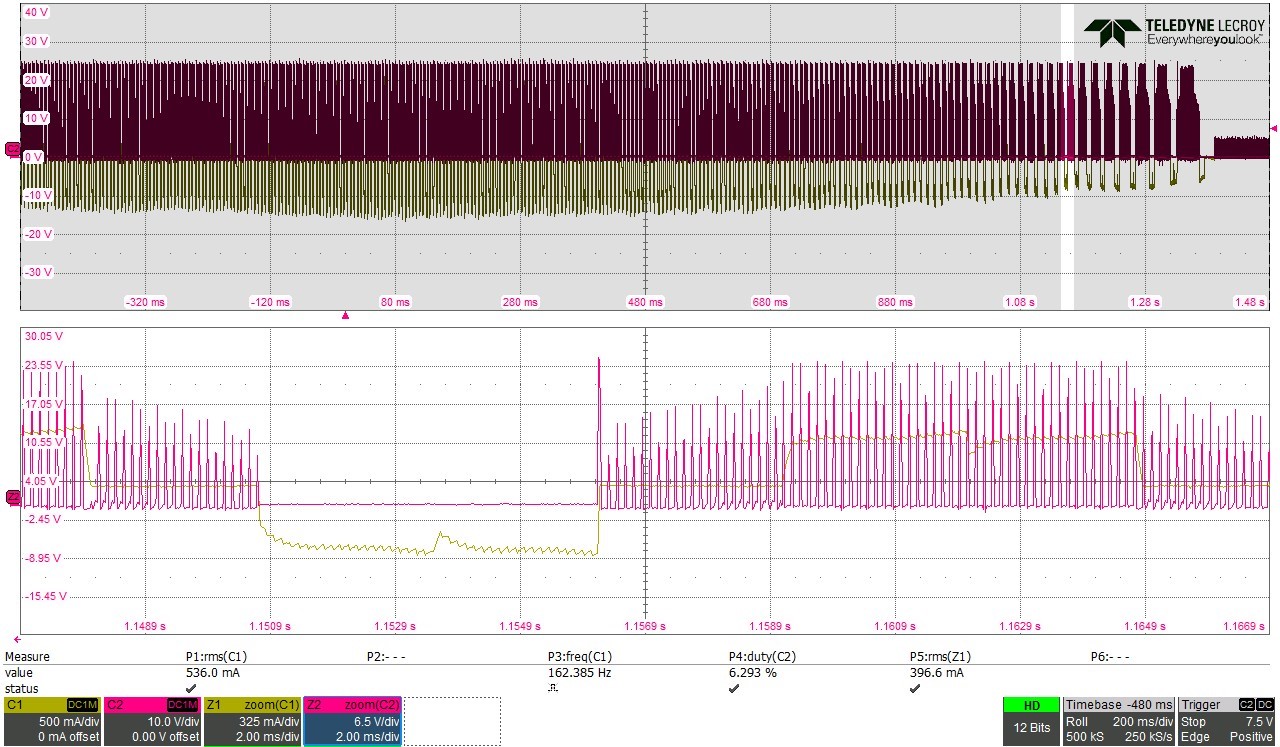
I've noticed that the PWM to the motor is disabled while the motor changes Phase ( trapezoidal phase shift).

when using 20Khz PWM - iI'ts not always occurring,

On the 50Khz PWM cycle I see it all the time.

Also I'm working with a DC brushless motor, and I've tried a few PWM frequencies for the control -18/20/50 Khz.

I was thinking that the faster the Frequency the better.

but it seems like the most smooth operation was with 18KHz, 50 Khz had a "grinding" effect.

I used a pure sinus PWM for both, the driver is limited to 1A. So at the peak of the sinus, I get current limits, but the most grinding is at slower speeds .

Also the motor is 24V winding, we use 32V operation.

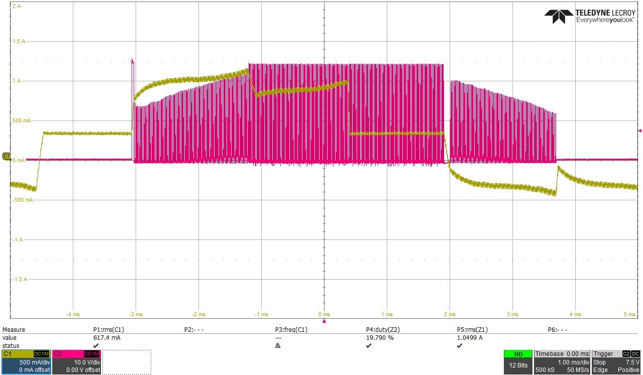
Pictures are attached.

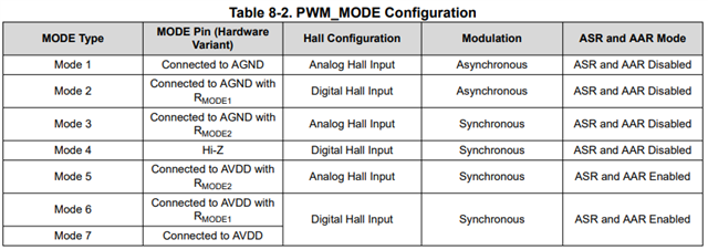
Also For smooth operation - what should I put in  the ASR and AAR  (Active Demagnetization) ? or they dont have any effect ? 

same for the slew rate ?

  • Hi Liran,

    I will take a look at this and get an answer to you by the end of the week.

    Regards,

    Hong


  • Hi Liran,

    May you specify which images use which frequencies of PWM? Is C1 (the green waveform) one of the phase currents, while C2 is the PWM into that phase?

    If so, you would expect to see PWM turned off when the current is low while some other phase has PWM turned on, as this is part of 6-step trapezoidal control, which you can learn more about in this video (https://www.ti.com/video/6011229676001).

    May you also point out on the scope capture what you mean by grinding?

    Regards,

    Hong

  • HI, Yes I Probably missed The connection of voltage and current.

    The Current probe is connected to one phase and the Voltage is connected to the other, that's why there is a mismatch in the image.

    But still I wonder about the break in the Voltage (on the voltage timeline, between the time the PWM is enabled - high 30V, and the time you see the BeckEMF - I guess this is the time the voltage drops)

  • Hi, I can't point out the "grinding" on the scope images, it's something we feel on the Axis with the motor. 

    when we use 18Khz PWM we get a smooth motion , when we use 50Khz we can feel as if the axis has sand on it..

    mainly I'm talking about very low speeds.

    And also we are seeing the current limit to 1Amp, so the actual PWM we can use is up to ~22% at 18Khz and ~30% at 50Khz, 

    Also with the current limit we can reach an RMS of 0.5Amp at 18Khz and ~0.65Amp at 50Khz.

  • Hi Liran,

    I am unsure what you are referring to exactly in the image. May you repost the image you are referring to with "the break in the voltage" highlighted?

    In your second reply, are you intentionally limiting your current to 1A, or do you want to change that? The current limit is a peak current limit.

    Regards,

    Hong

  • we set the Ilim to 1amp, which is the motor rated current.

    this is to prevent burning  the motors with the maximum driver current.

    see image bellow, I guess the break in the voltage is linked to the jump when the phase switches  (see two arrows bellow)

    Also, any idea why 18khz is causing smoother operation than 50Khz ? seems to be the opposite to logic.

    (on the other end 50Khz provides more RMS current then 18Khzm so maybe the driver and PID is more "jumpy")

  • One more question - 

    We are comparing the TI driver to a Torque (current controlled ) driver. 

    The Torque control driver works much smooter, especially in low speeds.

    Can I count on the PWM output to match the current output? 

    for example- is setting the PWM to X% and then setting it to 2xX% (for example 10% and 20%) will provide double the current ? is it linear? 

  • Hi Liran,

    Thank you for clarifying your questions. I will go investigate these matters and get to you by the end of this week.

    Regards,

    Hong

  • one more issue, I'm reading the ASR and AAR modes , and it seems there is some mistake in the data sheet . 

    the ASR (Automatic synchronous rectification ) - works on Asynchronous mode .

    and the AAR (Automatic Asynchronous rectification ) - works on synchronous mode . 

    seems it should be opposite

    Also table 8-7 does not have an indication for working in Async modulation. although the details for ASR do explain this mode.

  • Also ( sorry, I keep reading and keep having issues) 

    section 8.3.12 cycle by cycle current limit specify in figures 8-36 and 8-37 that when using synchronous recitifcation mode- the FET will be set to brake mode.

    But in Register_5 (offset = 7h) there is an option to specify what the FET will do - ILIM_RECIR, 

    so what is true ? can I control what happens to the FETs during Ilim through the register, or the state is determined by the selection of Synchoronous or Async ? 

  • Hi Liran,

    There is no issue with asking questions; that is what I am here for. Though, I will need time until the end of the week to answer these questions. I will keep you posted.

    Regards,

    Hong

  • Hi Liran,

    For the gaps in the voltage PWM; the rest of the operation seems fairly normal, so those transients could just be spikes. This could occur with a low inductance motor.

    For the PWM, if it is using more RMS current at higher frequencies, it could be hitting the current limit more often, which would cause unsmooth operation.

    ASR and AAR fall under active demagnetization, while synchronous/asynchronous modes refer to PWM, so they are different things. In summary, PWM modulation decides the switching patterns of the FETs, where in synchronous modulation the PWM is equal and opposite. You can see this in Table 8-4 in Section 8.2.3.4, where the HS has PWM and the LS has !PWM (opposite).

    ASR/AAR can be enabled at the same time (in fact, they are either both enabled or both disabled), and are for reducing losses to the FET body diode. This previous thread explains their function well (https://e2e.ti.com/support/motor-drivers-group/motor-drivers/f/motor-drivers-forum/1003893/drv8316revm-how-to-use-active-demagnetization-on-drv8316revm/3709632).

    Finally, your last question is related to the previous one. Figures 8-36 and 8-37 are illustrating states that can occur; brake and coast. Brake corresponds to ASR because ASR turns ON the low side FETs to stop the body diodes from conducting, and coast corresponds to AAR because AAR turns OFF the low side FETs when the current is low and decreasing to prevent reverse current.

    The current limit only activates when the current through the low side FET exceeds the configured current limit. Note that AAR and ASR trigger in different situations. Therefore, ILIM_RECIR controls what you want to happen when the current limit is exceeded while ASR/AAR are automatic.

    Regards,

    Hong

  • Hi Hong. 

    I Still don't understand -

    In section 8.3.11.1.2 - ASR, figure 8-32 the PWM mode looks like it's Asynchronous (PWM_LS applied is always off). 

       (BTW- the section number is wrong.. should be 8.3.11.1)

    In section 8.3.11.2 - AAR, figure 8-33 the PWM model looks like it's synchronous (PWM_LS  applied is opposite to PWM_HS)

    In general what is recommended to use with BLDC motor (resistance ~3Ohm, Inductance ~1.3mH) - I worked with Synchronous mode and ASR\AAR disabed and now I switched to Async mode (AAR and ASR Encabled - but according to the modes table is not available) - It's now much better in terms of motor behavior

  • one more issue - in tables 8-4. 8-3 , Stop mode - I assume it means brake? , the actual drivers output doesn't match this ( all are set to L, but the Low side should be set to H)

  • Hi Liran,

    I will investigate and discuss these with my colleagues and return to you by Friday.

    Regards,

    Hong

  • Hi Liran,

    The PWM modes are what you think they are (figure 8-32 is Asynchronous PWM and figure 8-33 is synchronous PWM). It might be helpful to not think about the full names of ASR and AAR, as they are a separate concept from PWM modes.

    Figure 8-32's description says "this mode [ASR] supports turning on the low-side FET during the low-side diode conduction". This triggers because when the LS is off, the current decays through the body diode, which is inefficient.

    Figure 8-33's description says "when AAR mode is enabled, the current during the decay is monitored and the low-side FET is turned off as soon as the current reaches near to zero". This triggers because when the LS is on (opposite of HS), that can cause the current to become negative.

    It's recommended to have ASR/AAR enabled for all motors except very low inductance motors, but your 1.3mH motor would not be considered low inductance.

    Finally, for tables 8-3 and 8-4, Stop refers to when the device stops operation, since brake would turn on the low side FETs.

    Regards,

    Hong

  • O.K, So the way I see it is the following -

    Auto Asynchronous rectification In PWM mode - is only working with Synchronous mode. (figure 32).

    Auto Synchronous rectification in PWM mode - is only working with Asynchronous mode (figure 33).

    Actually, Both are doing the same - opening the Low side FET when the diode is conducting.

    Strangely the name is opposite the actual PWM mode.

    Also It doesn't fit the PWM_MODE table, which indicates the ASR\AAR are only enabled in Synchronous mode.

  • Hi Liran,

    ASR turns on the low side when the diode is conducting while AAR turns off the low side when it detects low current to prevent negative current. They both are turned on or off at the same time in this device.

    Table 8-2 is for the MODE pin on the Hardware variant of MCT8316Z. The EVM has the hardware variant. Since there are only 7 voltage levels, the amount of PWM modulation, hall configuration, and active demagnetization (AAR/ASR) configuration combinations are limited. On the SPI device, you can use EN_AAR and EN_ASR to turn these on or off with synchronous or asynchronous PWM modulation (although both AAR and ASR need to be enabled for either to work).

    Regards,

    Hong