This thread has been locked.

If you have a related question, please click the "Ask a related question" button in the top right corner. The newly created question will be automatically linked to this question.

DRV8874: Enters fault mode if even small load is present when coming out of sleep mode

Part Number: DRV8874
Other Parts Discussed in Thread: DRV8873,

Here is my situation. I can't seem to use this device under load without it entering a fault condition. I connected an electronic load at 0.5 amps, and when pulling nSleep high, the nFault pin is pulled low and the device output is disabled. Curiously, if I pull nSleep high before turning the load on, it works perfectly when I turn the load on. In summary,

  • No load (just some small LEDs) - works perfectly
  • Load turn on after setting nSleep high - works perfectly
  • Load present before turning nSleep high - enters fault mode

I tried a load from 0.2 amps up to 1.0 amps, and the result is independent of the load - both being in fault mode or not fault mode. The only exception is no fault occurs for extremely small loads of a few milliamps. My motor voltage is 24 volts.

What am I missing here? How can I resolve this problem?

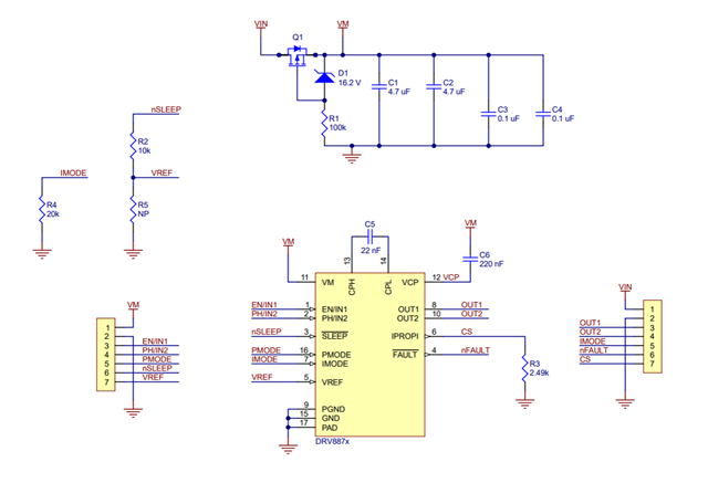
In case you need a reference circuit, I am reproducing this problem with this simple breakout board from Pololu - https://www.pololu.com/product/4035

Here is their schematic:

  • Hello Scott,

    Can you provide the nFAULT signal. I want to understand what type of fault is occurring. 

    In the meantime, We will attempt to replicate this phenomena using the DRV8873 evaluation board.

    -Pablo

    Applications Engineer

  • Is this what you need?

  • Hello,

    Thank you for providing the information.

    The nFAULT signal seems to point to an OCP fault (overcurrent). 

    What is the measurement of the load current while the driver is in this fault state? is it close to 0A.

    -Pablo

  • I measure 0.2v across the load (with a 24V input) when in the fault state, so I expect the current to be very close to 0A.

  • Hello Scott,

    We attempted to replicate in the lab but no success. I think the issue is probably caused by the electronic load. Can you try to run it again but use an power resistor or a motor?

    Regards,

    Pablo Armet

  • Sure thing. I first tried it with a 24 ohm resistor (@ 24V), so about 1.0A load. It worked just fine. I then tried again with the motor I am using (which also was throwing a fault). It still throws a fault. The motor is a 24VDC linear actuator motor which with no load draws around 0.6 to 1.1 amps by my measurement.

    I took another screenshot of the scope output, this time with the load on channel 2 (@10x probe):

    I noticed the previous pulses (from the electronic load) are absent now. What kind of fault is it throwing now? And what do I do about it? Even under load, this motor should pull around 4 amps, so I would think it would work with this driver IC.

    Thanks again for all the help.

  • Scott,

    Do you happen to know what the capacitance is across the motor terminals?  This is likely the cause of your issue.  I = C*dv/dt.  If the current exceeds the Iocp level in the device, there will be an OCP fault.  

    Quick check to see if this is the issue is to put a large inductor (22-33uH or so) between the outputs and motor terminals.  That will isolate the capacitance from the outputs and smooth the current.  If you have a current probe, you should be able to see the spikes on the switching transients.

    Regards,

    Ryan

  • Ok. I have made some progress, but am still having problems related to the large startup current spike. My problems previously were related to:

    1. The sensed current was exceeding Vref, which I had set to 3.3V. That is fixed (for now) by leaving Vref floating
    2. The imode state was either a 20k to ground (level 2) or floating (level 4). By tying it directly to ground (level 1), I was finally able to activate the actuator motor. 

    So, while I am able (for now) to energize the motor, I am still getting large startup current spikes along with an occasional fault mode entered. This is after inserting two 15mH inductors (one on each output line). Below is an oscilloscope output from connecting the motor directly (still leaving the 15mH inductors in place) to 24v (bypassing the DRV8874 driver altogether). As you can see, the B channel shows current, 1A = 0.1V (supposedly; I haven't calibrated the current probe yet), but it is likely, 1A = 0.05V, which using the first current to voltage mapping, the startup spike is 10amps, and using the 2nd one, it would be 20 amps! You can also see that this spike lasts about 30ms.

    Given this new data, do you have any advice on dealing with this large startup current spike? While it seems a bit large, it doesn't seem to be unusual for a motor to have such a spike. Should I be using a different chip? This test is not even under a load. The steady-state current under load is expected to be around 3 amps, whereas the current with no load is around 1 amp or less.

  • Daniel,

    1. The sensed current was exceeding Vref, which I had set to 3.3V. That is fixed (for now) by leaving Vref floating

    The VREF pin should not be left floating. It is not recommended. If you want to disable the current regulation, the IPROPI pin should be connected to GND and VREF tied to 3.3V. 

    2. The imode state was either a 20k to ground (level 2) or floating (level 4). By tying it directly to ground (level 1), I was finally able to activate the actuator motor.

    Level 1 does not report current chopping on the nFAULT pin and also the outputs are not latched during an OCP fault. With level 2, it is being reported. 

    Given this new data, do you have any advice on dealing with this large startup current spike?

    The best way is to regulate the current during startup. However, if the current is not enough to overcome the motor inertia and get it to spin, you'll need to look at other drivers with higher OCP threshold. Can you set the IMODE to level 1 and configure VREF such that the current chopping limit is below the OCP threshold.

    Regards,

    Pablo ARmet

  • That last post was very helpful. I set Vref = 3.3V, Tied imode to Gnd (level 1), and I used a 700 ohm resistor to ground from iPropi which gives a max current of just over 10 Amps. With this configuration, everything seems to be working just fine. I do have a few more questions though:

    1. I measured the current via iPropi, and the startup current is around 8.5 Amps, dropping to less than 5 Amps within 20 millisecs, and a steady state current of less than 3 Amps shortly thereafter. Do you see any problem with this startup current level?

    2. The spec sheet is rather vague on bulk capacitance on pin VM. I am using a total of 10uF. Is this sufficient?

    Thanks again for all the help. It is really nice to finally get it working.

  • Hi Scott,

    1. I measured the current via iPropi, and the startup current is around 8.5 Amps, dropping to less than 5 Amps within 20 millisecs, and a steady state current of less than 3 Amps shortly thereafter. Do you see any problem with this startup current level?

    8.5Amps is close to the 10A typical overcurrent level for this device which is 10A. And the minimum level is 6A which is below the start-up current. Can you set the current limit to 6A and see if the motor spins? If it does work well, I recommended setting the current limit to 6A to avoid potentially overcurrent protection disabling the outputs. 

    2. The spec sheet is rather vague on bulk capacitance on pin VM. I am using a total of 10uF. Is this sufficient?

    10µF will not be sufficient for your application due to the high current. A bulk capacitance => 100µF would be better.

    The bulk capacitance will be dependent on your current, voltage ripple, and other parameters. This video explains in detail what to consider when selecting a bulk capacitor. Hopefully this helps.

    Regards,

    Pablo Armet

  • I don't seem to have any trouble setting the max current lower as you suggested, and it seems my circuit is working well now. I do have one more odd question.

    In my breadboard circuit (which I referenced at the beginning), I was able to actuate the motor in both imode 1 and 2 states (the latter via a 20k resistor) with the initial current spike being limited as suggested. However, in my PCB design, I can only operate in imode 1, but not 2. The only difference I can see between the two designs is the PCB version has a lower current limit. The breadboard design limits current to 6 amps, and the PCB is limiting it to 4.5 amps.

    Would this current limit difference cause it to trip into an overcurrent fault in imode 2, but not 1? 

    What is the difference between the two imodes and when should one choose one over the other?

    Y'all have been very helpful, so I just wanted to express my appreciation for the excellent support.

    Thanks again.

  • Hello Scott,

    Would this current limit difference cause it to trip into an overcurrent fault in imode 2, but not 1? 

    The only difference between the two modes is that IMODE2 has cycle-by-cycle current regulation and current regulation is reported on nFAULT pin. Are you observing an actual fault with the PCB? is the nFAULT dropping LOW and disabling the outputs? Are you using resistors as load or an actual motor?

    What is the difference between the two imodes and when should one choose one over the other?

    I mentioned the main differences in my reply above.

    It would be interested to see if increasing the current limit to 6A on your PCB resolves the issue. 

    Regards,

    Pablo Armet