This thread has been locked.

If you have a related question, please click the "Ask a related question" button in the top right corner. The newly created question will be automatically linked to this question.

Questions about BLDC trapezoidal commutation and Hall sensors

Hi,

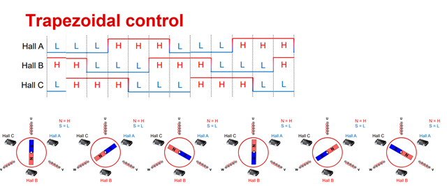
This is a question about BLDC trapezoidal commutation.

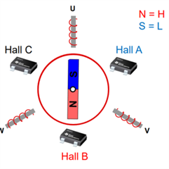
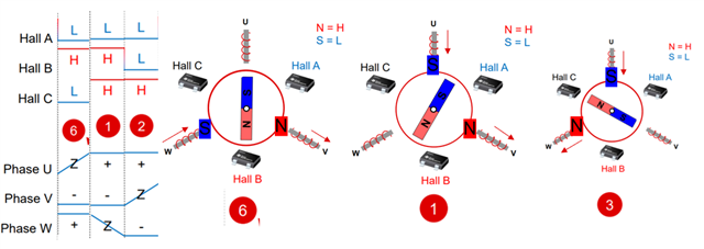
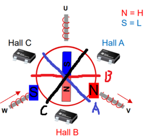
We all know that each Hall sensor changes its output every 180° in trapezoidal commutation, so for the Hall sensor and the rotor, the output of the Hall sensor will change at which point the rotor's magnetic pole moves?

For example, in the lower left corner of the following figure, why does the Hall sensor start to output L when the N pole of the rotor is aligned with the U phase of the motor? Is it because the sensing range of the Hall sensor is 120°, when N and U are aligned, it enters the sensing range of the Hall sensor? Or is it that the rotor magnetic field strength at this moment has reached the threshold for the sensor output to change? If the latter, wouldn't permanent magnets of different field strengths cause the rotor to change sensor output at different positions?

This question confuses me, hope you can help me out.

Thank you so much.

  • Hi Yunsheng,

    Are you referring to this image in your example and why Hall B and Hall A are High and Low, respectively?

    Regards,

    Hong

  • Hi Hong,

    Forgive me for not labeling the picture clearly. I relabeled the picture and gave an example of three steps in the trapezoidal commutation. I think these are bipolar hall sensors, so it keeps the output 180°, but the question raised is still not understood.

     
    Regards,
    Yunsheng Luo
  • Hi Yunsheng,

    You can visualize when the hall sensors change by drawing one line across the diameter of the circle, perpendicular to the line from the hall sensor to the center of the circle.

    The blue line determines what Hall A will be. Since the south pole of the magnet is in Hall A's half, S = Low output for step 6. For Hall B, the red line determines what it outputs. N = High output for Hall B for step 6. Repeating for Hall C gives a low output.

    So, a hall sensor changes when a new pole of the magnet "enters" its half. A good visualization of this, as well as more information about how trapezoidal commutation with sensors works, is in this TI Precision Labs video about Trapezoidal Commutation at 5 minutes and 13 seconds.

    https://www.ti.com/video/6011229676001

    Regards,

    Hong

  • Hi Hong,

    I totally get it, thank you so much for the answer.

    Regards,

    Yunsheng Luo