This thread has been locked.

If you have a related question, please click the "Ask a related question" button in the top right corner. The newly created question will be automatically linked to this question.

micro-stepping control of stepper motor

Hi,

          My application involves rotating a stepper motor, which is connected to a pump, in micro steps. For this purpose I have choosen a PWM driver IC - DRV8432. I have interfaced it with a ARM7 processor which generates the required PWM pulses and feeds to the driver IC and the driver's output is connected to the motor. I have tested this setup on various stepper motors and they are rotating satisfactorily. But, now I want to know the motor I am rotating, is rotating with how many number of micro steps. I mean what code I have written to generate those PWM pulses, is for how many micro steps. Is there any fourmula which relates PWM frequency to no. of micro-steps? Please help!

  • Hi Santosh,

    The number of microsteps is how many times you change the motor current value, or in this case your PWM duty cycle, on a per full step basis.

    For example, if you are generating a sine wave by PWMing the INx inputs and with a variable duty cycle mimicking the sine wave shape, you must have changed the PWM duty cycle x number of times from sine wave angle 0 to sine wave angle 90. Whatever this x value is, that is your degrees of microstepping.

    Conversely, if you are never changing the PWM duty cycle, but only which INx input sees the PWM signal, then you are operating in full step, in which case there is no microstepping operation at the moment.

    Hope the info helps. Best regards,

    Jose Quinones

  • Hi Jose,

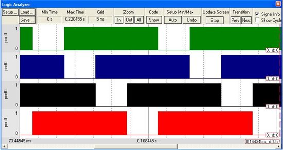
                     Thank you very much for your reply. Actually, I'm applying PWM signals to 4 poles of the bipolar stepper motor like shown in the picture attached

    Here I'm overlapping the 4 pole's signals. I'm also attaching the zoom view of this picture


    Here the duty cycle of the 4 pwm signals is 25% and is fixed. I'm not varying the duty cycle but overlaping the sequences. I got this idea from a practical pump applicaion. There i verified by CRO that, the motor was running with such kind of signals. Then tried to make it by my own. Is there any microstepping applied here. If yes, can you please tell me how is it achieveing microstepping here?

  • Hi Santosh,

    I analyzed the algorithm and I must ask: is the motor actually moving in an acceptable fashion, or just vibrating? The diagrams do not show which stepper signals are being exercised, so I am assuming the order is A+, A-, B+, B- from top to bottom. If so, you are applying switching magneitc fields to a phase while the other phase is non energized.

    The more I look at this scheme, the more I wonder how can the motor be moving. But I am not a motor, so there is a chance there is something I a missing here.

    What I do believe should in fact work, however, is using this scheme with a unipolar stepper motor instead of a bipolar stepper motor.

    If your stepper has six wires, merge both center taps and connect them to VM. Then apply the PWM to the four resulting phases. A unipolar stepper motor is in essence a four phase brushless dc motor. Do note, that instead of applying the PWM for a duration of 270 electrical degrees, the convention on driving unipolar stepper motors is to apply the PWM during 90 electrical degrees on a per phase basis. However, I believe your implementation should work as well, as it is following the four phases being generated with a 90 degrees out of phase angle.

    Now, whether this algorith is used to drive a bipolar or a stepper motor, I don't see any form of microstepping being issued here as the current level per winding is only one. Hence, if the motor moves, it will be under the influence of full steps.

    Hope the info helps. Best regards,

    Jose Quinones

  • Hi Jose,

    I'm again thankful to you for your reply. I'm sorry that, I forgot to mention the signal's energization order. So these are A+, B+, A-, B- from top to bottom respectively. I applied these signals to a 15 ohm, 23mH, 1A bipolar stepper motor with Vm (PVDD in DRV8432) of 15v. I found that the motor was vibrating. Then I gradually increased the PVDD and I found that at 20v the motor started rotating. Further I did some experiments on this and I observed that for the same motor when I'm increasing the duty cycle of those PWM signals the motor is rotating at lower supply voltages and when I'm reducing the duty cycle, I need higher supply voltages to rotate the motor. Is this something related to torque of the motor? What do you think, if the above mentioned PWM sequences are correct, is the motor is running with microsteps?

  • Hi,

    Can anybody help me regarding the above mentioned posts?

  • Hi,

    If you couple the mottor shaft to a high resolution encoder, you will be able to establish a relation between PWM pulses and shaft rotation.

    For example, if you use a 1000 ppr encoder, you will get 1000 pulses for 360 degree rotation of the shaft.

    hope this helps..

    Regards,

    Jayant

  • Hi,

    Can anybody tell me from the above matters, whether I'm applying microstepping or not? If yes, please tell me how. I just want to know what logic I have applied is for microstepping or full step only. Because here I'm not varying the PWM duty cycle but, overlaping the poles energization signals by 90 degree apart. If you can observe 3 pole's signals are high at any instant while the 4th one is low. So is it any way of achieving microsteps? Please help! 

  • Hi Santosh,

    From the captures it is hard to know how the motor is reacting to the applied signals. I am inclined to say this is not microstepping, although it almost resembles half step a little bit.

    We have a good deal of application notes detailing how to definitely achieve microstepping, so maybe you should start from here. Unless you are trying to be novel and devise a new energization method, in which case your experimentation is always welcomed.

    http://focus.ti.com/general/docs/lit/getliterature.tsp?literatureNumber=slva416&fileType=pdf

    There is also an article I wrote on the matter:

    http://www.eetimes.com/design/embedded/4217719/A-simple-algorithm-for-microstepping-a-bipolar-stepper-motor?Ecosystem=embedded

    Hope the info helps. Best regards,

    Jose Quinones

  • Hi Jose!

    Thanks for replying. I went through the references you had given. I also got some idea on how to do microstepping. But if you could please excuse me, I'll stick to my query which was, if the above mentioned waveforms are in half/full step, then why somebody will try to achieve these in the above manner? I mean we can achieve these in a manner as mentioned in the material you have mentioned, why shall we split into small pulses? Can you please tell me? Because those waveforms are taken from a running motor. I just want to get some idea on what manner the motor is rotating.

  • Hi Santosh,

    I am afraid I am lost and am failing to follow the current question.

    But I will answer what I believe it is and that is why do we want to use microstepping. There is tons and tons of discussions out there on why you want to use microstepping, but it can all be summarized in a few points such as:

    1. overall softer motion

    2. less resonance effects at certain stepping rates

    3 the ability to move the motor at very slow speeds without lots of torque ripple

    Hope this is the answer you were looking for. Best regards,

    Jose Quinones