This thread has been locked.

If you have a related question, please click the "Ask a related question" button in the top right corner. The newly created question will be automatically linked to this question.

DRV8702-Q1: Help understanding Motor Waveforms

Part Number: DRV8702-Q1

Hi,

I have a DRV8720 conntected to 4x CSD18510 FETS. My motor is a brushed DC motor powered from 24V.

The driver is operating in Mode=High-Z where I am supplying the PWM directly.

In the picture below I have:

1. Green = Motor Phase A (measured at motor)

2. Yellow = Motor Phase B (measured at motor)

3. Blue = IN2 (measured close to the DRV8702)

4. Purple = IN1 (hand annotated, but also measured close to the DRV8702)

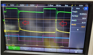
We note that during switching off of IN2 (falling edge of PWM) we get what looks like a phase reversal from the FETS.

Can anyone help explain why this is happening?

Thanks.

  • Hello Stomp,

    If we look at this table below 

    then you can see when IN1 = 1 and IN2 = 0, then you are in forward drive, which is shown in the figure below. When you switch to the case where IN1 = 0 and IN2 = 0, then you are in the High Z (coast) state where all the FETs are off and the current that was flowing now flows in the opposite direction through the body diodes of the FETs. The voltage across the motor is the reverse of what it was, which is why there are voltage spikes at the output whenever it transitions to the IN1 = 0 and IN2 = 0 state. The current eventually decays and the voltage correspondingly also decays. However, one thing to note is that if you don't want those spikes then you could consider slow decay mode, which is when IN1 and IN2 both equal 1. This means that you have to make IN2 = VDD instead of GND. 

    Best,

    Keerthi

  • Thankyou Keerthi,

    You mention in your second paragraph about not wanting those spikes. I am trying to understand from a system efficiency viewpoint.

    1. If after each falling edge of PWM IN1 we have the diodes conducting, where does this energy go, does it go back into the battery?

    2. If I put IN2 = 1 during PWM would this brake the motor after each PWM cycle and use more energy or cause the motor to slow down?

    Thanks!

  • 1. The motor can be thought of as an inductor and resistor in series, so if you look at is an LR circuit, then you can see how the current eventually decays to zeros as it circulates through the motor.

    2. When you set IN2 = 1, then you are in slow decay, which means that the current circulates through either both of the high side FETs or both of the low side FETs (In this case both of the low side FETs). This is called slow decay because the current decays slower than the fast decay. This is often used to maintain torque when braking. Whilst fast decay is used for coasting.

    Refer to this App note for more details:

    Current Recirculation and Decay Modes (Rev. A)