This thread has been locked.

If you have a related question, please click the "Ask a related question" button in the top right corner. The newly created question will be automatically linked to this question.

DRV8718-Q1: when use DRV8718S-Q1 EVM's PWM control mode have the oscillation occurs on PWM falling edge

Part Number: DRV8718-Q1

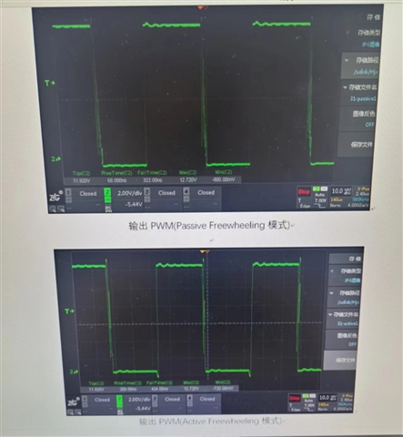
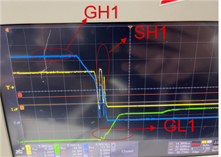
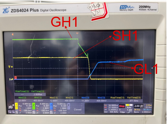
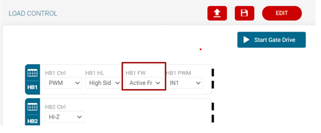
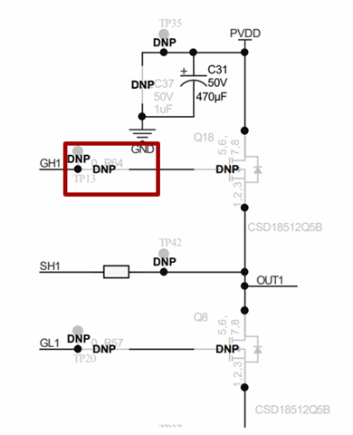
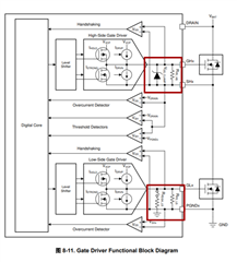
When I use the DRV8718S-Q1 EVM to driving the motor , I set the EVM in PWM control mode to control the high-side MOSFET.PWM's frequency is 20Khz. But i find have an oscillation will occur on the falling edge of the PWM , which can be partially eliminated in the active freewheel mode, but cannot be completely eliminated, and this abnormal waveform will be fed to the GH pin by the output. Have you ever encountered this? 

problem, and is there a solution?

The oscillating waveform is as shown in the figure below

  • Hi Luke,

    I will do my best to recreate this issue in the lab. 

    In order to more accurately recreate the issue, could you please send me your motor voltage, and a screenshot of the GUI parameters being used?

    Best,

    David

  • Hi,

    1) The phenomenon of oscillation on the falling edge of the PWM wave occurs when the motor is discharged, and the MOSFET is turned off at this time,

    The EVM board's voltage is 12V .The motor is an inductive load.

    2) about the GUI configuration , I  I set the EVM in PWM control mode to control the high-side MOSFET.PWM's frequency is 20Khz.Other configurations are default configurations.

    Do you know the reason for oscillation phenomenon,and is there a solution?

  • Hey Luke,

    Just curious, did you change any of thesettings in the Smart Gate Driver tab of the GUI such as IDRVN/IDRVP./VGS_TDRV/TDEAD?  Often tweaking these settings for your specific motor and application is the easiest way to get the best result.  I would focus on trying different IDRIVE settings (IDRVN/IDRVP).  Try different combinations and see if you can get a more clean waveform.  You can also try tweaking the rise and fall times in the Advanced Gate Driver page.  there are many settings available in this device and finding the "best" settings for a given motor can be a lot of guess-and-check since each motor model is different.  

    Cheers,

    Jacob

  • Luke,

    It is always best to keep the conversation going on E2E.  I am copying waveforms below.  Also, when you take pictures of waveforms with a camera...make sure to capture the whole screen of scope so we can see the timing information.  Timebase is very important to helping to solve problems.  

    I would like to consult you

    1. why SH has a falling edge oscillation and how to eliminate it? I and my customer tried to modify the parameters in "smart gate drivers" but it didn't solve the problem.
    2. Under this GUI configuration, do you have a similar SH pin waveform phenomenon in the laboratory?

    The GH pin has the same waveform as the SH pin, but the MOSFET is in the off state. Therefore, our customer thinks that there is a problem with the internal circuit of the DRV8718S-Q1 chip, which leads to the conduction of the GH pin and the SH pin. Have you ever had this problem before?

    First, can you help with the timebase in the scope capture?  To help debug, try setting VGS_TDRV to a higher value and see if you can tell an improvement.  Do NOT try any of the advanced gate drive features or make changes in these tabs...will just add more confusion at this point.  

    Lets keep the conversation going here please.

    Regards,

    Ryan

  • Ryan,

    Thanks a lot for your reply. I will continue to assist my customers to test according to the method you said and give you feedback in time.

    I also want to give you more
    information about the oscillation
    Does the oscillation of the SH pin have something to do with the fact that the motor is an inductive load?

    When I use a resistive load or no load connected, SH pin is no such oscillation.
  • Hi Ryan

    I have solved the oscillation phenomenon on the falling edge of the SH pin, and the current waveform is shown in the figure 
    below.

    My solution is:
    1) Adjust HB1 FW to active Freewheeling mode. As shown below

     
    2)
    Increase the R64 resistor value on the EVM board to 70 Ohm .
    As shown below


    The above two solutions need to be carried out at the same time to eliminate the oscillation of the SH pin

    I want to consult you two questions

    1)Why can the oscillation of the SH pin be eliminated after the R64 resistance value is increased?

    2)Why can the oscillation of the SH pin be eliminated after the active freewheeling function is turned on?

    What is the function of the active freewheeling function?

    I am so confused about the above two questions .can you help me?


  • To help debug, try setting VGS_TDRV to a higher value and see if you can tell an improvement.

    Thanks for your reply,

    I have tried the your suggestion about setting VGS_TDRV to a higher and reducing gate driver current.

    But the SH pin oscillation phenomenon does not slow down.

  • Luke,

    That is interesting as lowering the drive current is effectively doing what inserting a resistor in series with the gate is doing.  

    Active freewheeling means you are enabling the opposite FETs when recirculating the current.  So, you go from a DRIVE state to "free-wheeling" state by enabling the opposite FET so re-circulating current flows through the FET instead of the body-diode of the FET. 

    Passive free-wheeling means you are placing one of the FETs into a HIZ state by driving the gate LOW.  This means the re-circulating current will flow thru the body diode of the FET.  

    How is your motor load connected to the EVM?  Is it a uni-directional motor (only spins one way) and you are connecting between one 1/2 bridge and GND or one 1/2 bridge and VM?  Or is it is a bidirectional motor connected across 2 1/2 bridges?

    Regards,

    Ryan

  • How is your motor load connected to the EVM?  Is it a uni-directional motor (only spins one way) and you are connecting between one 1/2 bridge and GND or one 1/2 bridge and VM?  Or is it is a bidirectional motor connected across 2 1/2 bridges?

    Hi,

    Thanks for your reply.

    I use the a half-bridge in the EVM . the motor is connected between the OUT1 pin and GND in the EVM. As shown below

    What I want to explain to you is that reducing the resistance and turning on the active freewheeling function need to be done at the same time to solve the oscillation phenomenon. 

    I will continue to adjust the parameter settings as you said and continue to test to confirm whether there is an effect of slowing down the oscillation phenomenon

  • At present, my customer thinks that the oscillation waveform of the SH1 pin and the GH1 pin is the same because there is a problem with the internal circuit of DRV8718-Q1. I'm trying to explain to my customer that our DRV8718-Q1 chip doesn't have an internal circuit problem.

    I find the DRV8718 datasheet shows a clamp diode between the GH and SH pins, but not between the GL and SH pins. as shown above.

    Therefore, my customer thinks that the waveform of the SH pin oscillation is the induced electromotive force generated by the inductive load of the motor during the switching process of the MOSFET, and it flows back into the GH pin through the clamp diode. I don't agree with the client's statement.

    So I would like to ask you two questions so that I can better explain this backflow phenomenon to customers.

    1) What is the function of clamping diode between GH pin and SH pin, why is clamping diode not needed between GL pin and SH pin.
    2) Will the voltage of the SH pin flow back into the GH pin through the clamping diode to affect the chip operation of the DRV8718-Q1, or even worse, the backflow voltage will directly damage the DRV8718-Q1? This is what my clients worry about the most

    can you help me!

  • Hi Luke,

    1) What is the function of clamping diode between GH pin and SH pin, why is clamping diode not needed between GL pin and SH pin.

    The clamping diode between the GH pin and SH pin is used to keep the gate voltage at a constant voltage to in order to not damage the FET. 

    2) Will the voltage of the SH pin flow back into the GH pin through the clamping diode to affect the chip operation of the DRV8718-Q1, or even worse, the backflow voltage will directly damage the DRV8718-Q1? This is what my clients worry about the most

    Any backflow voltage from the SH pin will flow through the body diode of the FET, not the clamping diode. 

    Best,

    David