Dear forum members
I need some help with DRV5353 working at 48V battery.
Several months ago I asked for help in the same matter, somehow the customer didn’t order and the issue remained un resolved. Now we supplied units to the customer and a serious problem popped again.
When the battery which supply the motor driver is in fully charge around 53VDC the DRV5353 (not always) stop working. (Blown up)
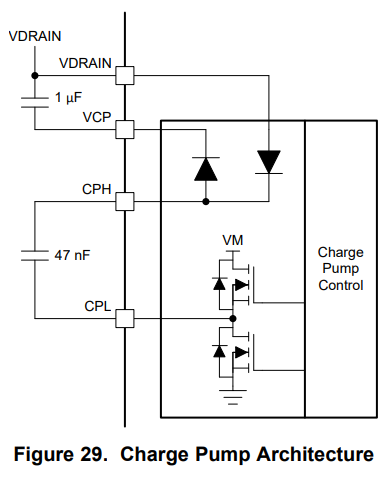
In such situation the DRV5353 consume large amount of power, and the VCP voltage is equal or slightly higher than the VM voltage. In some cases, the resistance between the VCP pin to Ground is 2 Ohm and in some cases several kΩ
We tried to:
1- Reducing the drive current, I Drive to 100mA/150mA IDRIVEP_HS or IDRIVEP_LS = 0011b
2- Reducing the high current time T Drive to 1uSec. TDRIVE = 01b
3- Schottky diode between the VCP PIN and VM to the Ground to prevent negative transient on VCP signs. But nothing helps.
I wonder if the DRV5353
1- Has a parasitic diode between VCP and GND?
2- how the IC regulate the Vcp voltage? is it by internal zener diode? (Can such regulation stand the power created by the charge pump 47nF low ESR capacitor driven from VM (at 53V)
3- How the high side gate drivers, + the current sources consumes the power when the Vcp+VM is 64V?
Your prompt answer will be highly appreciated.
We already sold over 2000 unit running at 24V without any major issue. The problem is only on 48V systems.
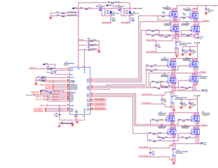
The schematics is simple and very close to the application. The IC is connected to same Power GND with all the relevant pins.

-
Ask a related question
What is a related question?A related question is a question created from another question. When the related question is created, it will be automatically linked to the original question.