I have a question about DRV8245-Q1 to control motor
I am testing with the following configuration:
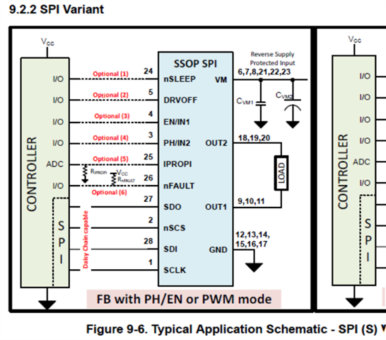
Functional configuration is SPI(S), and SPI communication, PWM mode
The testing process has been followed.
1. Functional configuration is SPI(S) variant.
setting nSLEEP to HIGH, sending CLR_FLT command after tREADY.
After that, nFAULT pin changed to HIGH
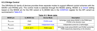
2.After setting some register, Set DRVOFF to LOW, and similarly control EN/IN1 and PH/IN2 as below,
EN/IN1  ( 5Khz PWM used )
PH/IN2 
or
EN/IN1 
PH/IN2 
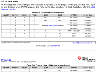
3 when I read STATUS1 or STATUS2 register, and the ACTIVE bit continues to be reversed to “0” and
The STATUS Byte is receive “ 0xC0” .
But the system does not go to the ACTIVE state, so which part has a problem?
In the manual, if the nSLEEP pin is HIGH and the DRVOFF pin is LOW, STANDBY => ACTIVE
But, why couldn’t the drv8245 go to the ACTIVE state ?
And the Outputs of OUT1 (drv8245 9, 10, 11 pins) and OUT2 (drv8245 18, 19, 20 pins) are always all about 0.3V,
** Register settings are as shown below
COMMAND = 0x89 /* Clear error, lock SPI IN, unlock CONFIG */
CONFIG1 = 0x5F /* VM > 18V, spread spectrum enabled, retry enabled */
CONFIG2 = 0x04 /* no extensions, no off state diagnostics, ITRIP 1.98 */
CONFIG3 = 0x4B /* TOFF time 30us, SR 9.8, PWM mode */
config4 = 0x00; /* TOCP 6us, OCP 100%