Hello TI team,
I have been DRV8899-Q1EVM kit to drive a stepper motor. I tried to operate the stepper motor using the available GUI from TI, and it is working fine. I am able to operate the motor by sending the SPI commands to the motor driver. But the main thing is that, I want to operate this motor driver using an external MCU, so I have removed all the on-board resistors (R3, 4, 6, 7, 9, 11, 12, 14, 15, 16, 17) which connects the motor driver with the on-board TI MCU. Now,, I have connected my own MCU device and connected the following pins to the header (3.3V, VREF=2.0V, nSCS, VSD=3.3V, SDO=MISO, SDI=MOSI, SCK, DRVOFF and nSLEEP and GND).
My MCU is acting as a SPI master device and providing the commands to the motor driver to drive the stepper motor.
The steps which are followed to do the SPI operation with driver:
1. DRVOFF is high. 500ms delay. nSLEEP is high. 500ms delay. nSLEEP is low. 500ms delay. nSLEEP is high. 500ms delay. DRVOFF is low. 500ms delay.
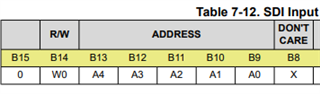
2. To rotate the motor a single step (18 degree, in this stepper motor case). I am sending 0x0A and 0xFA (for CTRL3 register) (sending 1-byte at a time as SPI buffer is of 8 bit for this MCU).
Now the problem is that, the motor is not rotating and the motor is getting heated a lot within 5s. The current consumption reaches up to 500mA. But there is no movement in the motor. I just want to move the motor a single step (18 degree) so a single SPI command for CTRL3 reg and setting the bit 6 for SPI_STEP will cause the motor to move a single step.
But anyhow, the motor is not able to rotate.
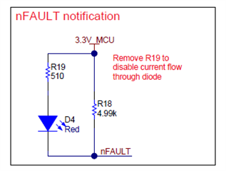
During the receiving of the SPI signals from motor driver. I am getting 0xC000, every time. On-board FAULT led is never lit high, which indicates that there is no fault the SDO value show that 0xC0 has fault and SPI error.
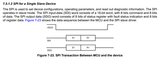
For the sake of SPI signals reference, I am attaching the SPI signals that are transmitted from MCU to motor driver.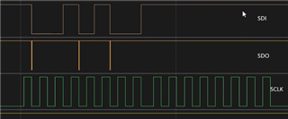
nSCS pin is not the picture, but before nSCS pin is low when SCLK goes high and SCLK pin is low when nSCS goes high.
Please help me out to solve the issue.
Thanks,
Vivek Karna