A related question is a question created from another question. When the related question is created, it will be automatically linked to the original question.
If you have a related question, please click the "Ask a related question" button in the top right corner. The newly created question will be automatically linked to this question.
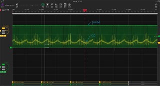
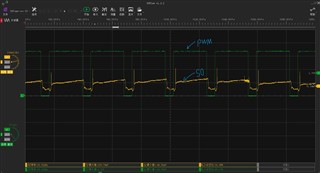
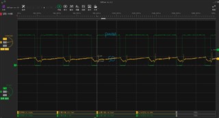
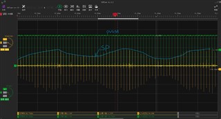
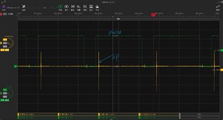
Thank you for your response. The description of my question might not be sufficiently clear. My intention does not pertain to a PWM period; rather, it spans over a longer duration. As observed in the first image, there is an upper envelope on the SO pin signal. The second image provides a close-up view of the peak of the SO signal, while the third image offers a close-up of the trough of the SO signal. I posit that when the PWM duty cycle remains constant, the motor speed and the current passing through the motor will also be consistent. Consequently, the SO signal will remain same during each high-level period within a PWM cycle.
The spikes are due to the output switching. You will need to filter these out when sampled with external MCU. Our newer devices like the DRV8705 offer a blanking feature to remove these spikes, but unfortunately that is not in the DRV8701.
Current decaying when PWM stops is part of what I explained earlier.
I appreciate your response. However, it seems the core of my issue hasn't been entirely grasped yet. While I can address the spikes through software, my concern lies in a different facet. Specifically, when the PWM duty cycle remains constant, I anticipate a consistent motor speed. Accordingly, the waveform of the SO pin should also remain consistent between PWM periods. Contrary to this expectation, the SO pin waveform varies: at times, the SO pin is higher (as seen in the second picture), and at other instances, it is lower(as seen in the third picture). This fluctuation results in a waveform of the SO pin that exhibits a wavelike envelope when zoomed out(as seen in the first picture). This instability in the SO pin signal prevents me from accurately determining its voltage.
Do you have a current probe? That is really the only way to determine if the SO pin is responding as expected. Comparing to an actual current measurement would be helpful.
I don't have a current probe; I only have an oscilloscope. I'm doing tests on TI DRV8701EVM and DRV8701EVM_GUIv1.0 to rule out any hardware issues. However, I've noticed an experiment result that confuses me. When the configuration is constant, the "Motor Current" exhibits a wide range of variation(0.03A~0.14A), as shown in the link below. I can't understand why the current isn't staying relatively consistent.
Is the SO output also fluctuating? The delta voltage with a 10mohm sense between 0.03A and 0.14A is 1.1mV drop across the sense resistor. Offset of amp alone is 50mV.
Given above, that variation is better than I would expect.
Thanks for the video, I see the fluctuation you mean. I agree with Ryan's above answer that this small amount of variation is probably normal/unavoidable with this part. The DRV8701 is one of our first ever motor driver gate driver, and we have made significant improvements over the years in latest releases and the issue you are seeing is likely one of the things we have improved. I'd highly recommend looking into the DRV8706-Q1 instead. (You can use automotive part in non-automotive application, no worries).