Because of the holidays, TI E2E™ design support forum responses will be delayed from Dec. 25 through Jan. 2. Thank you for your patience.

This thread has been locked.

If you have a related question, please click the "Ask a related question" button in the top right corner. The newly created question will be automatically linked to this question.

DRV8718-Q1: Question of Low IQ Powered Off Braking

Part Number: DRV8718-Q1

In the power off braking function of DRV8718, there are the following four configuration methods for the use of the function. For option 2: external OV detect, as shown in the red box, a pull-down resistor of 1Mohm and a series resistor of 10Kohm are added respectively.

What is the role of these two resistors here? How to calculate the resistance value of this resistor? For example, can it be larger or smaller than 1Mohm? Can it be bigger or smaller than 10Kohm?
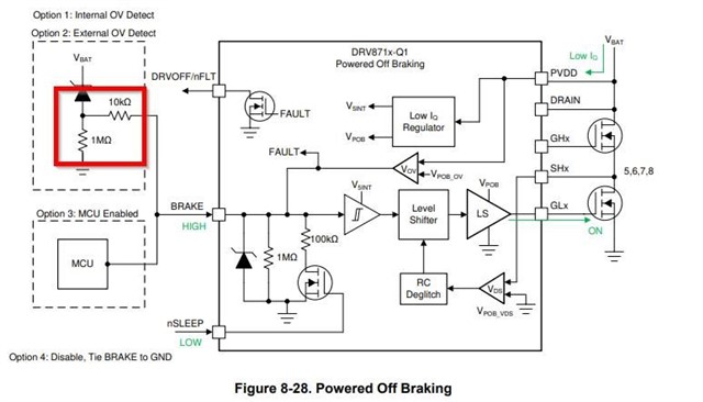
The content of this part is located on Page52-53 of the Datasheet, 8.3.8.2 Low IQ Powered Off Braking (POB, BRAKE).

  • Hi Link,

    The 1 MΩ resistor is used as a pull-down resistor for the brake pin to reduce quiescent current draw during low power sleep mode. The brake pin can receive a logic high signal from battery supply through the Zener diode due to the internal voltage clamp. The 10 kΩ is used to limit current during the high enable from battery supply.

    These values are configured based off internal voltage clamp and for impedance matching of the pin. It is recommended that they are not changed.

    If powered off braking is not used it can be disabled by connecting BRAKE pin to PCB ground.

    Is there any specific reason why the resistor values need to be changed?

    Best,

    David

  • Hi David,

    Thank you for your reply. My team wants to arbitrarily configure the overvoltage threshold of the overvoltage trigger.

    According to the description in option2: An external Zener diode can be added to the BRAKE pin to create an overvoltage trigger that is lower than the internal overvoltage monitor.

    Then under the configuration of option 2:

    how to determine the trigger voltage threshold of this lower overvoltage trigger? 

    Can this lower voltage threshold be arbitrarily configured?

    If it is configured as option 2, how does it realize the function of enabling power-off braking?

    Best regards,

    Link

  • Hi Link,

    Under option 2, the trigger voltage threshold may be configured lower than the overvoltage trigger by configuring the resistor divider (1 MOhm, 10 kOhm) to the desired voltage level. The power-off braking will be realized when voltage cross the comparator threshold.

    Best,

    David

  • Hi David,

    Thank you for your reply. My team has a few more questions:

        There is already a pull-down resistor of 1Mohm inside, why do we need an external 1Mohm, the resistance between the two in parallel is reduced to 500Kohm.

        What is the clamping voltage value of the internal zener diode?

    Best regards,

    Link

  • Hi Link,

    The internal 1 MΩ resistor is to reduce quiescent current draw during low power sleep mode to ensure minimal power loss over an extended period of time. The external resistor is used to set the desired voltage trigger threshold and can be configured appropriately.

    The Zener diode voltage would be relative to the maximum voltage of the BRAKE pin which is VPVDD + 0.3 V, which can be found in the datasheet.

    Attached is an application brief about the DRV8718 and its integrated protection against back EMF overvoltage:

    https://www.ti.com/lit/an/slla527a/slla527a.pdf

    Best,

    David

  • Hi David,

    Thank you very much for your reply and support. 

    In my understanding, the working principle of Option2 is: when the external Zener diode is reversed conduction, the internal Zener diode will clamp the BRAKE pin to HIGH, and the Powered Off Braking function will be enabled at this time. So I thought the voltage threshold was determined by the external zener voltage. But according to your description, my understanding seems to be wrong.

    In your first reply, you said that it is not recommended to change the value of these resistors. If I can change these values, what is the relationship between the voltage threshold and the value of the external resistor? If I want to set trigger threshold to 20V, how should I calculate the resistance of the external resistor? (this is just an example)

    Best regards,

    Link

  • Hi Link,

    Yes, you are correct. I was mistaken in my first response. The external resistors can be changed to set the trigger voltage threshold. The value of the resistors can be calculated by a voltage divider calculation to determine the desired threshold. 

    Best,

    David

  • Hi David,

    According to the block diagram, due to the existence of the Zener diode, it seems that the trigger voltage cannot be calculated simply through the resistor voltage divider equation.  Maybe I misunderstood, can you help me to answer the following questions?

    If I want to set trigger threshold to 20V, how should I calculate the resistance of the external resistor? (this is just an example)

    Best regards,

    Link

  • Hi Link,

    Thank you for your question. Let me jump in this discussion.

    1) If you are OK with ~30V trigger threshold, please use option 1( BRAKE pin is left not-connected/HiZ) as option 1 on datasheet page 51.  

    2) If you want to have ~20V threshold, you can use option 2 configuration. Then we need to pay attention BRAKE pin VIH/VIL. 

    While PVDD<20V, BRAKE pin should be less than 0.6V. While PVDD>20V, BRAKE pin should be >1.8V for your goal.

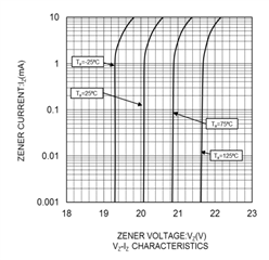
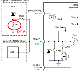
    One example is to have Zener diode with ~20V like bellow. If PVDD is low like ~15V, no current come to EXT_R (1Mohm), therefore BRAKE pin should be lower than 0.6V. If PVDD is ~22V@25C,  Zener diode provide some current on EXT_R then voltage at EXT_R should go above 1.8V. Therefore, BRAKE pin voltage also go above 1.8V.

    regards

    Shinya Morita

  • Dear Both,

    Thanks for detailed clarifications.

    Best regards,

    Link

  • Hi Shinya,

    Thank you for all your assistance. I have a few more questions:

        1. Regarding the external resistors, why are their resistance values 1Mohm and 10kohm? 

        2.  Still the previous example, assuming there is no EXT_R (1Mohm), If PVDD is low like ~15V, also no current come to EXT_R2 (10kohm), BRAKE pin is also lower than 0.6V. If PVDD is ~22V@25C, after the current passes through EXT_R2 (10kohm), and then flows through the internal 1Mhom resistor, the voltage of BRAKE pin seems to reach 1.8V.   What is the role of EXT_R (1Mohm) and EXT_R2 (10kohm) here? 

    Thank you again for everything you've done.

    Best regards,

    Link

  • HiLink,

    Thank you for your questions.

    1. When external zener turned on, this 10Mohm x  Zener current generate voltage. If this resister is too small, zener current cannto make high for VIH of BRAK pin.

    10Kohm is kind of soft isolation between 10Mohm at Zener and BRKAE pin input.

    2. Actually 10Mohm + 10Kohm is not critical value. As you pointed out, you can make it work without 10Mohm + 10Kohm or another way. 10Mohm + 10Kohm is just example to make it work. Directly connecting Didoe to BRAKE pin, DRV may have high current goes into BRAKE pin from Zener diode.. It depends on Zener Diode characteristic. With this way, current into BRAKE pin and voltage on BRAKE pin is limited - more safe than direct connection.

    If you want to choose another way for external circuit, it is OK. 

    regards

    Shinya Morita