This thread has been locked.

If you have a related question, please click the "Ask a related question" button in the top right corner. The newly created question will be automatically linked to this question.

DRV8962: how to connect a single motor

Part Number: DRV8962

Hi Team,

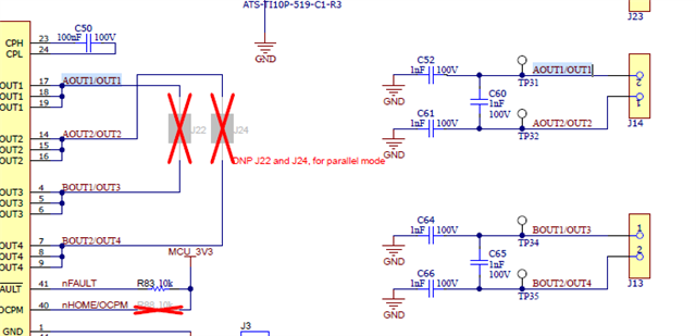
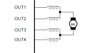
1) In the EVM the schematics are as described in the left image, could you help share how to connect a single motor (as described in the right image) which was taken from the DRV8962 datasheet:
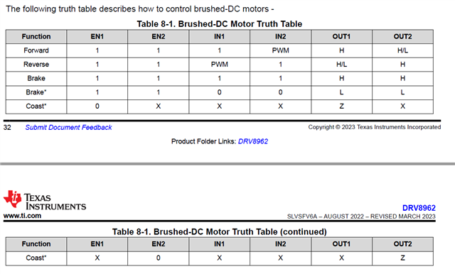
2) What are the operation mode for operating a single brush DC motor ? ( only the following table for dual DC brush connection are found)
Could you help check this case? Thanks.

Best Regards,

Cherry

  • Hey Cherry,

    1) In the EVM the schematics are as described in the left image, could you help share how to connect a single motor (as described in the right image) which was taken from the DRV8962 datasheet:

    Populate J22 and J24 with a jumper or a short wire, or just use two cable clips to connect the test points together (OUT1 to OUT2, and OUT3 to OUT4).  Then connect the motor to the OUT1 and OUT3 screw terminals. 

    IN1 & IN2 need to be tied together. Also IN3 & IN4 need to be tied together.  Remove onboard IN2 and IN4 shunts from J4 and J8, and use clips or jumper wires to connect IN1 to IN2 (on driver side (right side) of J4), and similarly tie IN3 and IN4 together with a jumper wire.  

    2) What are the operation mode for operating a single brush DC motor ? ( only the following table for dual DC brush connection are found)

    Follow the INx --> OUTx table (Table 8.1) you posted, just treat "IN1" as "IN1&IN2" since they're tied together.  And think of the "IN2" column as "IN3 & IN4" since they're tied together.  Same for the OUTx, OUT2 == OUT3 & OUT4.

    Regards,

    Jacob