This thread has been locked.

If you have a related question, please click the "Ask a related question" button in the top right corner. The newly created question will be automatically linked to this question.

DRV8873-Q1: Can't set MODE to independent half-bridge

Part Number: DRV8873-Q1
Other Parts Discussed in Thread: DRV8873S-Q1EVM

We are using the H-bridge motor driver DRV8873S with part number DRV8873SPWPRQ1 and  we're trying to use the outputs as independent half bridges which we do get to work on the development board but when changing the MODE register on our prototypes they seem to be stuck in PWM mode.

We are using three in series in daisy-chain SPI configuration but on our prototypes we have also tested with single SPI configuration.

Also since the print on top of the IC (from Digikey, see attached image) didn't match the development board exactly we also ordered extra from Mouser and tested with and got the same result.
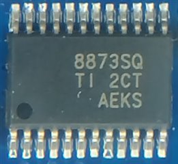
DRV8873S on prototype

We have tested with the following parameters on both our prototypes and the DRV8873S-Q1EVM:

IC1 0x72
IC2 0x0c
IC3 0x46
IC4 0x18
IN1: 0
IN2: 0
DISABLE: 0
nSLEEP: 1

IC1-IC4 is the registers in the DRV8873S, and the rest is the pin inputs.

On the development board this sets OUT1 to sourcing and OUT2 to Hi-Z.

On our prototype it sets OUT1 to sourcing and OUT2 to sinking.
Testing with all combinations of OUT1_DIS ,OUT2_DIS, EN_IN1 and PH_IN2 shows consistency with PWM mode on our prototype (OUTx_DIS has no effect and both ENx low sets both outputs to Hi-Z).

  • Hello Joachim,

    Also since the print on top of the IC (from Digikey, see attached image) didn't match the development board exactly we also ordered extra from Mouser and tested with and got the same result.

    The marking label on the IC displays information about the IC fabrication. The marking can be different for various IC batches. All ICs have been tested to ensure they work before being shipped out.

    Have you read back the register values to confirm that it matches what you wrote? If there were any problems writing to the MODE bits, the MODE will default back to PWM.

    Another possibility is that a UVLO fault occurred and reset the logic circuitry resetting all register to default value. Have you check that there are no faults?

    Regards,

    Pablo Armet

  • Yes I have read out the registers after setting them and currently I'm reading out the registers every second
    and I see the expected values, IC1 = 0x72 and IC3 = 0x46 with the result being OUT1 sourcing and OUT2 sinking.
    Both FAULT and DIAG are 0x00 for all three ICs and STATUS returns 0xc0.

    I have now tested to replace the DRV8873S on the devkit DRV8873S-Q1EVM with one of our
    new DRV8873SPWPRQ1 and it does work there as it should with the same register setup.

    Regards

    Joachim

  • Joachim,

    Thank you for providing the request information.

    I am a bit confused. You said in your original post that the issue does not occur in the evaluation module (DRV8873S-Q1EVM) but you said in your latest reply:

    I have now tested to replace the DRV8873S on the devkit DRV8873S-Q1EVM with one of our
    new DRV8873SPWPRQ1 and it does work there as it should with the same register setup.

    Is the issue occurring in both the Devkit and your own board?

    Regards,

    Pablo

  • The issue does not occur on the Devkit. That has been tested both unmodified and when replacing the DRV8873SPWPRQ1 with the new ICs that we had ordered.

    So the ICs seems to be OK since they work on the Devkit but for some reason it does not on our prototypes. I am going to spend some time today with a mixed signal oscilloscope to record and compare all signals on both the devkit and our prototypes which I hope may bring some clarity to the issue.

  • Hi

    I have now found that I had missed the following part in the datasheet (after seeing the short transitions on the dev board):

    "7.3.1 Bridge Control [---] In the SPI version of the device, the mode setting can be changed by writing to the MODE register in the IC1 control register because this device version has no dedicated MODE pin. The device mode gets latched when the DISABLE signal transitions from high to low."

    Since we had tied DISABLE to ground the mode change never activated. I don't see any other way of activating it so a rework will be the solution for us.