Other Parts Discussed in Thread: MSP430FR6043
Hello Community,
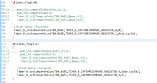
To operate the valve, I'm using the DRV 8210 DSG. I'm generating PWM1 (TB0.1) and PWM2 (TB0.4) from the MSP430FR6043. By using ADC I am sensing the supply voltage Vs to achieve the required dc to run the motor.
i,e DC= (5 (required voltage) / Vs)* 100;
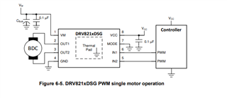
For PWM Mode, I connected the MODE to GND in Driver.
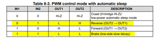
1. I verified the PWM generation at the MCU end; a) IN1 = 0 and IN2 = 1 (PWM) (Reverse); b) IN1 = 1 (PWM) and IN2 = 0 (Forward).
2. Next, I connect the MCU's PWM1 and PWM2 pins to the driver IN1 and IN2 ports. I checked the output from OUT1 and OUT2 and it is as expected.
a) OUT1 =Low and OUT2=PWM (Reverse)
b) OUT1=PWM and OUT2=Low (Forward)
A channel =OUT1 and B channel =OUT2
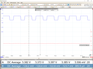
3. When I connect the motor to OUT1 and OUT2, let's assume I'm doing reverse operation, OUT1 = PWM (75% DC) and OUT2 = PWM (25% DC), it appears to be in complimentary mode.why?
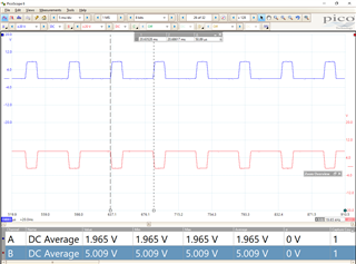
A channel =OUT1 and B channel =OUT2
I conducted the Test with various voltage, for some voltage the parallel voltage at OUT1 and OUT2 is 0. i,e (close) Vs=9V OUT1 =4.1v and OUT2=4.8v.
Please look the below table for your reference,
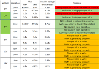
PWM generation from the MCU end is happening as predicted, however after I connect the motor to the DRV, the issues listed above start to occur.
How to fix these problems.
Thanks in advance,
Sarwath