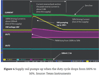
This thread has been locked.

If you have a related question, please click the "Ask a related question" button in the top right corner. The newly created question will be automatically linked to this question.

DRV8848: Want to understand the Vout waveform..

Part Number: DRV8848

Hello team,

My customer asked of waveform below and want to know why the output has the slope at a certain situation. (red rectangular)

I assumed that would be the slow decay but VINs are not show both 'high' and also the timing is 4s/div which is too large for slow decay.

Would you see and give your insight?

DRV8848 vout waveform

Best Regards,

Ernest

  • Hey Ernest,

    The slopes you highlighted are likely when the device outputs are in high impedance mode, like in the fast-decay mode during Mixed Decay mode.  

    Regards,

    Jacob

  • Hi Jacob,

    Thanks for your reply.

    Based on your comments and datasheet explanation on "7.3.5 Current Recirculation and Decay Mode", I and my customer checked more about the waveform highlighted above.

    Here're enlarged waveform and customer schematic.
    1) They do not use R_Shunt at xISEN pin.
    2) Motor winding currents are not shown at the points.
    3) This is happened at A-ch but not from BOUT channel. Exchanged the motors for Ach and Bch by switching connector and still resulted only at the A-ch showed slope.

    Would you let me know what causes the different decay at below 1) and 2) ?

    enlarge waveform

    schematic

    Best Regards,
    Ernest

  • Hey Ernest,

    I think the difference is from whether the driver detected a current beyond the chopping current threshold and decided it needs to hit fast or slow decay mode. 

    For your bottom right scope capture, see Figure 4 Supply rail pumps up when the duty cycle drops from 100% to 50% in the article Tips and tricks for testing, debugging brushed DC motors.  Same in your figure - sudden reduction in duty cycle (from 100% to 0%) causes the supply voltage to be pumped up by the inertia and speed of the motor that is still spinning.  

    Is there any specific issue you're having with the motor when you're seeing these waveforms that you're trying to debug?  

    Regards,

    Jacob

  • Hi Jacob,

    For my capture on the bottom right side, I tried to capture the reverse currents as you mentioned earlier in the post, and also zoomed the waveform but it doesn't see any reverse currents. I captured currents at one of the connector wire which is connected to the motor.

    For your bottom right scope capture, see Figure 4 Supply rail pumps up when the duty cycle drops from 100% to 50% in the article Tips and tricks for testing, debugging brushed DC motors.  Same in your figure - sudden reduction in duty cycle (from 100% to 0%) causes the supply voltage to be pumped up by the inertia and speed of the motor that is still spinning.  

    I don't think I understood right or not so I would like to clarify your comments above.
    Do you mean the waveform in the left side one? Because left capture has very thin currents slope when VIN2 is transit to 0. But right side waveform does not show any reverse currents.

    Please refer that above bottom images are 200us/div where as yours are 100ms/div.

    Is there any specific issue you're having with the motor when you're seeing these waveforms that you're trying to debug?  

    They said the motor shows 2~3 degrees difference(ahead?) than normal and think it could cause the mechanic damage. 

  • Hi,

    Thank you for your question. Monday September 4th is national holiday in US. Jacob feedback to you when he backs to office.

    regards

    Shinya Morita

  • Hey Ernest, 

    The waveforms show where it's switching from fast decay to slow decay.  The current spike in the second image is the current freewheeling through the body diode.  

    How much is your bulk capacitance?  And can you try to compare on an EVM so we can see if it could be related to your PCB schematic/layout?

    Regards,

    Jacob

  • Hey Ernest,

    Ahh apologies I didn't see that you had disabled current regulation.  I talked to my manager and he said that the spike you're seeing in the first picture is from the current that remains in the coil when you switch the inputs.  Then you don't see it in the second image because at that time there wasn't excess current remaining in the coil. So there is no chopping going on, the device outputs are following your inputs.  

    Regards,

    Jacob

  • Thanks for your reply Jacob.

    I'd like to check that my understanding is correct or not.
    For the timing 1) above, Vout spike to opposite direction(few msec) is due to the Iout currents, and timing 2) is not seen the Iout and so Vout voltage have slope to 0V because the motor spin is ramping down.
    And I 

    If my understanding is correct, then Vout spike at the timing 1) is made by DRV8848?

    And if customer want to remove the slope like time 2), then  can we set the Vin1, Vin2 as {1, 1} ?

    Best Regards,

    Ernest

  • I'd like to check that my understanding is correct or not.
    For the timing 1) above, Vout spike to opposite direction(few msec) is due to the Iout currents, and timing 2) is not seen the Iout and so Vout voltage have slope to 0V because the motor spin is ramping down.

    Yes, I believe so

    If my understanding is correct, then Vout spike at the timing 1) is made by DRV8848?

    It is made by the motor state, not the driver

    And if customer want to remove the slope like time 2), then  can we set the Vin1, Vin2 as {1, 1} ?

    Setting both high would put that bridge into Brake (slow decay) mode, that might solve the problem but I am not sure.  Give it a try!

    Regards,

    Jacob

  • Hi Jacob,

    Thank you for your reply. I will check these with customer.