Other Parts Discussed in Thread: DRV832X
Hello guys,
I am implementing FOC on a PMSM motor using DRV8323RS. I have a problem with the current values that I sample using an MCU+ADC, it does not match the current clamp probe that I assume to be my truth reference.
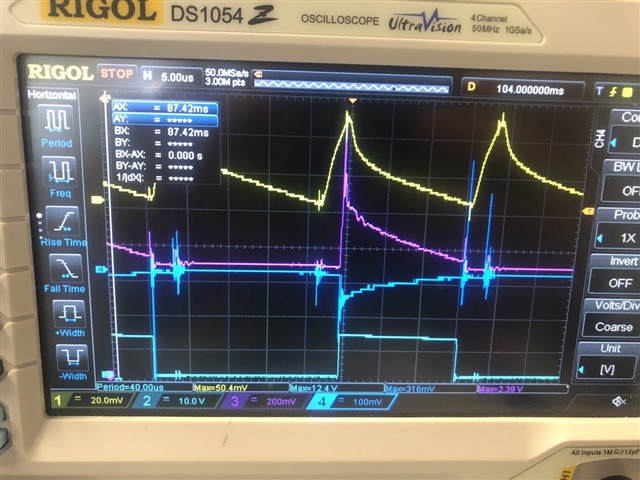
To understand the problem, I measured on oscilloscope the following signals :
- phase B current with clamp probe (YELLOW)
- Low-side gate GLB signal (BLUE)
- Amplifier output SOB (PURPLE), gain = 10
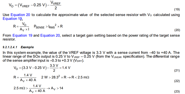
The DRV8323RS is set in bidirectional current mod, VDD = 3.3V and Rsense = 2 mOhm.
On the picture bellow, you can see, while motor running, the phase current descreasing (yellow), the amplifier output (purple) transiting from zero to non-zero when the low-side gate switches ON (blue).
At the measurement point, AY = 40 mV means the current value I = 40mV / 10 = 4 A
At the measurement point, BY = 1.764V means the current value I = (VDD/2 - 1.764) / (G_CSA * Rsense) = (3.3/2 - 1.764) / (10 * 0.002) = 5.7 A
The difference between probe measurement and above amplifier conversion is significative !

On the picture bellow, I increased the motor load and redid the same experimentation.
You can see, while motor running, the phase current descreasing (yellow), the amplifier output (purple) transiting from zero to non-zero when the low-side gate switches ON (blue).
At the measurement point, AY = 90 mV means the current value I = 90mV / 10 = 9 A
At the measurement point, BY = 1.93V means the current value I = (VDD/2 - 1.93) / (G_CSA * Rsense) = (3.3/2 - 1.93) / (10 * 0.002) = 14 A
The difference is still huge.

Finally, the last picture shows even bigger load currents.
At the measurement point, AY = 120 mV means the current value I = 120mV / 10 = 12 A
At the measurement point, BY = 2.05V means the current value I = (VDD/2 - 2.05) / (G_CSA * Rsense) = (3.3/2 - 2.05) / (10 * 0.002) = 20 A

Following the above observations, here are my questions:
- Are the fluctuation on SOB signal (purple) part of an expected transient phase ?
- What could be the reason of difference of shape and magnitude between line current (yellow) and low-side amplifier output SOB (purple) ?
- As this prevents me from measuring accurately the current with my MCU, what would be a potential fix for this problem ?
[EDIT]
I redid the same experiment at a higher rotation speed, which means higher voltage, higher high-side duty-cycle and smaller low-side duty cycle. Consequently, the GLB logic high period is even smaller and we can observe than the SOB fluctuations barely converge during the time GLB is high. (see picture bellow)
Thanks a lot for your help !!