This thread has been locked.

If you have a related question, please click the "Ask a related question" button in the top right corner. The newly created question will be automatically linked to this question.

DRV8424PEVM: Circular half step configuration for DRV8424PWPR

Part Number: DRV8424PEVM
Other Parts Discussed in Thread: DRV8424E, DRV8424, DRV8424EVM, DRV8426, DRV8428

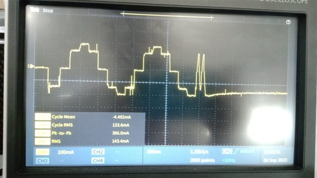
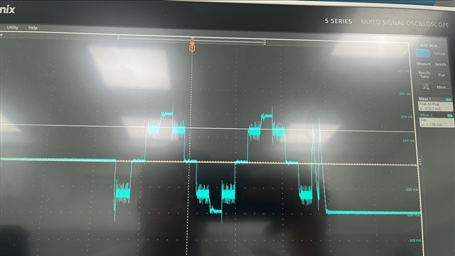
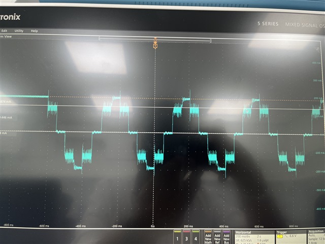
We are using DRV8424PWPR in our design. We have configured the motor driver in circular half step configuration. But if we measure the output current the waveform seems to be non circular. Could you please suggest how to configure the motor driver in circular half step configuration. Also attached the current waveform for your reference.
  • Hey Guru,

    Is this on the EVM or your own board?

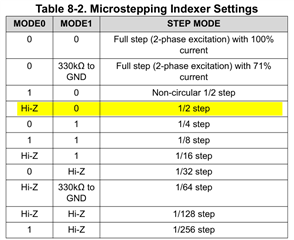
    Can you measure the voltage on the MODE0 and MODE1 pin?  As long as MODE0 is HI-Z (~2V) and MODE1 is LOW then it should be in 1/2 step mode.  Perhaps at the given motor speed and load it isn't obvious on the scope that it is in 1/2 step.  

    Regards,

    Jacob

  • It is our custom board. Yes, as you suggested we have configured M0 and M1 pins as per the data sheet (Mode0- Hi-Z and Mode1 - 0). Even after change the M0 and M1 configuration the output current wave form is not changing. What could be the reason?

    Step signal frequency - 13.2KHz

    Vref pin voltage -3.3V

    Voltage input -12V

    Motor load - 0.4A

    Measured M0 pin voltage - 2V

    Measured M1 pin voltage - 0V

  • Hey Guru,

    Ahh I think I figured it out.  My previous answer was incorrect - I was looking at the DRV8424 which has 1/256 microstepping built in, and I think you are too.  However, the DRV8424PEVM uses the DRV8424E device on it which does not have integrated microstepping.  The DRV8424E or DRV8424P support Phase/Enable (E) or PWM (P) intergaces but no microstepping built in.  Current regulation can be set using VREF_A and VREF_B pins, by adjusting this on the fly with a microcontroller you can achieve microstepping. 

    Can you confirm which device version is on your board, and if that's the device you designed for?  Our above discussion about the M0/M1 pins are applicable to the DRV8424.  Sorry their names are confusing.  

    Regards,

    Jacob

  • Hello Jacob

    Yes, I have verified that also. In our Board we are using DRV8424(Part Number-DRV8424PWPR) only. Also, we have tried to check the same in 

    DRV8424EVM but we are not able to get the circular half step. Please help us to get the required circular half step configuration as soon as possible Since it has major impact on our project schedule.

  • Hey Guru,

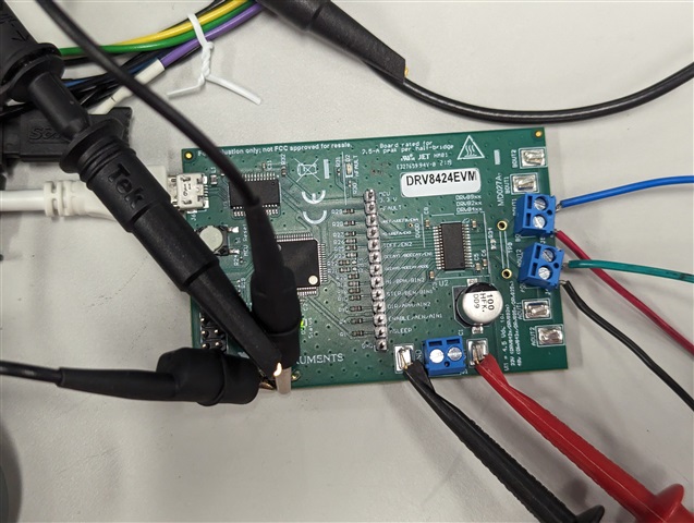
    Can you post a picture of your EVM, and a picture of the top of the DRV8424 device on your own board so I can see the markings on it?  

    Can you test another microstep setting like 1/16 microstep and see if that works?  Is it only 1/2 circular that doesn't work, or do no microstep settings work? 

    Regards,

    Jacob

  • Hello Jacob,

    I have double checked part on the EVM as well as the part on our Board. It is DRV8424. Even I tried to change the micro stepping to 1/4, 1/8 and 1/16. But unfortunately, none of them worked on the EVM and in our Board also. If possible, can you share the circular half step configuration current waveforms. 

  • Hey Guru,

    If you can give me photos of the EVM and the chip (or just type out the markings on the top of the DRV device) I can verify they are both the DRV8424 supporting microstepping.  The behavior you're describing all matches up with it being the wrong device and EVM that doesn't support microstepping. 

    You have the configuration correct for half-step configuration - M0 Hi-Z, and M1 LOW.  

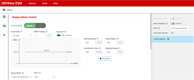
    You can test it on the EVM - open up the GUI (https://dev.ti.com/gallery/view/MotorDriversBSM/DRV84xx/ ), select DRV84xx, Toggle the motor driver from Asleep to Awake, set the Step Mode to 1/2 step (or 1/16 step for testing), Enable Driver Outputs, and press Start Steps.  For more info see the DRV84xxEVM GUI User’s Guide

    Regards,

    Jacob

  • Hello Jacob,

    I will share the photos by Monday. I will try with another EVM as well. Thanks for the quick response.

  • Sounds good, thank you as well! Sorry you're having these issues.  

  • Hello Jacob,

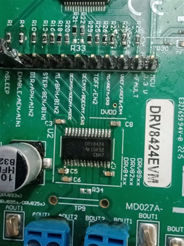
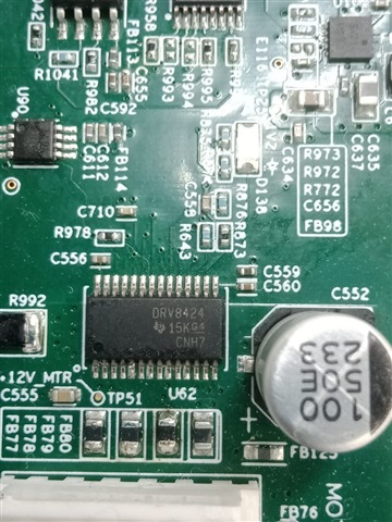
    Please find the attached images for your reference.

  • Hey Guru,

    I stand corrected - you're right, that's the EVM that supports 1/256 microstepping and your chip as well.  I checked and confirmed your chip is legitimate as well.  I hooked the EVM up to an oscilloscope and motor and tested it and mine is behaving as expected 

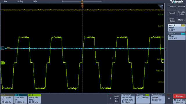
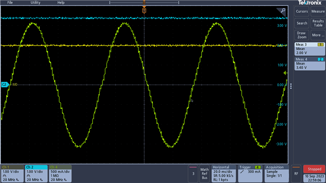
    • Yellow: M0
    • Blue:  M1
    • Green:  Current probe on BOUT1

    1/2 step - M0 is 2V, M1 is 0V.  

    Half Step

    Your waveform looks like the Non-Circular 1/2 step (M0 is 3.3V, M1 0V), shown in the image below: 

    Here's what another microstep mode should look like - 1/16 microstep

    So it worked for me on a DRV8424EVM, it should work on your board as well.  

    I tried various VREF settings and decay settings but the only way I could get a waveform similar to yours was with non-circular half-step.  

    Can you post your schematic so I can review it?  I don't know what could cause this issue besides your M0/M1 pins not being connected to the right pins or similar.

    Regards,

    Jacob

  • Hello Jacob,

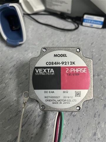
    Thanks for sharing detailed answer. I just wanted to know what Control mode on the EVM GUI is? What is the difference between speed and step in that? I have attached the schematics for your review. Also attached the part number of the motor we are using in our design. Please let me know how we can configure circular half step configuration for the motor.

    Part Number - C084H-9212K

    Manufacturer - Vexta

     mtr_drv_review_12_09_23 (1).pdf

    Regards,

    Guru Hegde

  • Hey Guru,

    Thanks for sharing detailed answer. I just wanted to know what Control mode on the EVM GUI is? What is the difference between speed and step in that?

    These don't change device settings, it just changes whether the motor runs indefinitely (speed) or if you want to have the motor only run a certain number of steps and then stop (Step mode).  In Step mode you can tell it to run 1000 steps and it should use the acceleration and max speed settings to accomplish the 1000 steps. 

    I have attached the schematics for your review.

    nFAULT is open-drain output so it needs a pull up resistor, recommend 10kΩ.  

    Your M0 and M1 pins are correct for 1/2 step.  M0 (pin 18) is left Hi-Z/disconnected with your DNP of R647.  M1 (pin 22) is pulled LOW via R1085.  

    Let me ask some coworkers for a second opinion on this.  Looks like a pretty standard stepper motor, thanks for sending part number.  

    Can you try removing R1085 so that M1 is set to Hi-Z, and see if the device starts outputting 1/128 step like it should? Trying to see if other microstep settings work for you.  The most helpful would be to set it to non-circular 1/2 step and compare that to circular 1/2 step and see if waveform is different at all.  

    Regards,

    Jacob

  • Hi Guru and Jacob,

    I would try to short ferrite beads FB125 and FB126. I can not see any decoupling capacitor between VCC_3V3 and GND.

    Guru, could you share motor datasheet and measure motor winding resistance?

    The first picture. Is timebase (400ms) and full scale current value (around 200mA) correct?

    Full scale current value should be (3,3/2)/1.32 = 1,25A. It looks like motor winding resistance is around 12V/0,2A = 60 Ohm and limits motor current.

    Regards,

    Grzegorz

  • Hello Grzegorz,

    The motor winding resistance is 30 ohm. 

    Full-scale current is 0.4A.

    Please find the attached image for your reference. Please let me know what the exact VREF value is required so that we will get the half step current waveform properly. 


    Regards,

    Guru Hegde

  • Hi Guru,

    It will be 0,4x1,32 = 0,528V or less due to motor windings temperature rise.

    To keep motor current at around 0.4A at speeds above 0 rpm. you will need higher voltage than 12V. I would start with 24V or change the motor for one with lower windings resistance.

    Regards,

    Grzegorz

  • Hello Grzegorz,

    It is redesign of the existing product. Earlier also they have used 12V for the motor. In the earlier motor driver, we are getting the half step waveform properly. Please find the below part number for the existing motor driver.

    Part Number- A3984SLPTR-T

    VREF pin voltage - 0.256V

    Input voltage - 12V

    Also attached the current waveform of the existing device for your reference.


  • Hi Guru,

    Then, please keep on lowering  Vref voltage till you get the same current waveform.

    Regards,

    Grzegorz

  • Hi Grzegorz,

    If we lower the VREF the motor is making some noise while moving. I just wanted to know what are the factors which affects the current waveform? How does lowering the VREF will produce the waveform similar to existing product. Also How does the input voltage will affect the half step current waveform?

  • Hi Guru,

    Lets try first get current waveform like the old one. Full scale current on old waveform is around 0,2A.

    Can you, set Vref to 0,2Ax1,32 = 0,26V, then if you have some noise, please try to use STDD or STRC decay mode?

    If you still have problems, please share current waveform, Vref and other settings and problems you experience.

    Is 30 Ohm measured value or just label value, we do need exact value of motor winding resistance.

    In case of excessive noise you can also try to set TOFF to 0, especially in STRC mode.

    PS. I think once you get promising results with DRV8424 you should switch to DRV8426 that would be better for such low motor currents.

    Regards,

    Grzegorz

  • Guru, 

    You should be able to test this all pretty easily with the EVM - I used the EVM and tested with our motor at all variety of VREFs and most VREF under 2V worked for me, but I had a larger motor than yours.  Can you test with the EVM first and let us know if that worked, and then try our suggestion of shorting the ferrite bead out?

    Regards,

    Jacob

  • Hello Grzegorz,

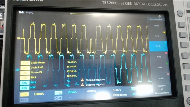
    I have tried with VREF- 0.26V. I am able to get the half step current waveform similar to existing. But I observed lot of noise in the current waveform. Also, motor is making noise while moving. I tried with different decay modes unfortunately no improvement. Attached the current waveform for your reference. Please let me know what the issue could be.
     

    Regards,

    Guru Hegde

  • Hi Guru,

    Ok, so we have some progress. Please, answer all below mentioned questions:

    Is 30 Ohm measured value or just label value? we do need exact value of motor winding resistance.

    - Have you shorted ferrite beads FB125 and FB126? If not, please short them and check if it made any difference

    - Have you placed any MLCC decoupling cap between VCC_3V3 and GND, if not please place some 0,1uF-1uF and check if it made any difference.

    - what is timebase for division for the last waveform?

    - what is your max. motor speed in rpm or pps for half-step?

    - at what speed did you notice noise?

    - does noise change significantly with speed?

    Best Regards,

    Grzegorz

  • Hello Grzegorz,

    I measured the motor winding resistance. It is 60 ohm.

    Yes I have shorted FB125 and FB126 in the Board.

    VCC_3V3 is used only for pull up. I don't think it requires a decap.

    Attached the new image for your reference.

    I have tried with different speed the noise will come only when the VREF is 0.26V. If the value of the VREF is more then there will not be any noise. But I am not able to get the half step current waveform at the output. Please let me know if you need any additional information. As the speed increase the noise will not be there. 

  • Hi Guru,

    You have not answered all my questions, so lets go with what we have.

    "I measured the motor winding resistance. It is 60 ohm." - That is what I suspected from the beginning. Your max. current limited by motor winding resistance is 12/60 = 0,2A and there is no point of increasing Vref for DRV8424 above 0,26V unless you want to go full step then there might be some marginal gain in going a bit over 0,26V.

    " If the value of the VREF is more then there will not be any noise. " - that means that noise is probably caused by current regulation.

    Lets go back to my former suggestion "In case of excessive noise you can also try to set TOFF to 0, especially in STRC mode."

    Please try to use TOFF 0 and 1 for different decay modes and check if it reduces the noise.

    Quite comprehensive explanation of noise sources in stepper motors and how to reduce the noise you can find in below application report

    https://www.ti.com/lit/an/slvaes8/slvaes8.pdf?ts=1694697019525&ref_url=https%253A%252F%252Fwww.google.com%252F

    I mentioned DRV8426 earlier but even more suitable driver for 0,2A current would be DRV8428 though it would marginally  lower max. motor current in your case.

    PS. If your motor is 6-wire uni-polar type then below mentioned Application Note would be very helpful to get a better performance from your motor and DRV8424.

    www.ti.com/.../sloa312.pdf

    Regards,

    Grzegorz