Our team recently discovered an issue with the recently released DRV8245S-Q1LEVM. The EVM fails to connect to the GUI, and the nFAULT LED doesn't display the status of the nFAULT signal on the microcontroller. This is due to the nFAULT trace from the motor driver not being connected to the nFAULT LED or the MSP430 that runs the GUI interface. This issue applies only to the PCB "MD048A". Previous versions of the EVM (MD048E2 or MD048E1) do not have this issue. It also does not apply to the hardware version of the EVM, DRV8245H-Q1LEVM.
There is a new GUI version that will allow the EVM to connect to the GUI without any hardware changes: https://dev.ti.com/gallery/view/MotorDriversBSM/DRV824x_DRV814x-Q1EVM-GUI/ver/1.0.1/ This will work on the online cloud version of the GUI or the local installed version. However, the nFAULT signal still will not be shown in the GUI without a hardware modification to the EVM.
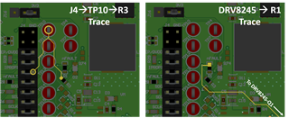
To fix this issue, a jumper wire must be added between the nFAULT signal from the motor driver (U1) and the nFAULT Test Point (TP10) or header jumper. The below picture shows the two traces we must connect:

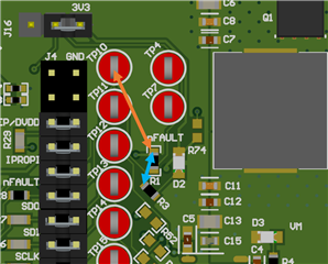
There are two simple ways to do this. You can connect a wire from the top pad of R1 to TP10 (orange arrow in below image). Or you can connect a wire from top pad of R1 to the top left pad of R3 (blue arrow below). Either of these will result in a fully-functional EVM. You could also connect the jumper wire from pin 26 (nFAULT) on the motor driver, but this will likely be more difficult than solder to R1.

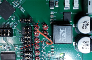
See below for the orange arrow solution applied to an EVM

We are working on applying this modification to all exiting EVMs in stock and correcting the build files so that this issue doesn't perpetuate on future EVM builds.

