This thread has been locked.

If you have a related question, please click the "Ask a related question" button in the top right corner. The newly created question will be automatically linked to this question.

DRV2510-Q1: IN+ IN-

Part Number: DRV2510-Q1

Hi Expert, 

My customer is using DRV2510-Q1 as the vibration feedback driver in their new project. They met one question and need your help to support. 

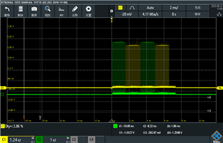
Below is the actual output waveform from the MCU. After connect with IN+/IN- of DRV2510-Q1, IN+ and IN- will be changed to same phase and introduce 1V DC offset. 

May you kindly give some suggestions for this phenomenon? Are there any wrong configuration? 
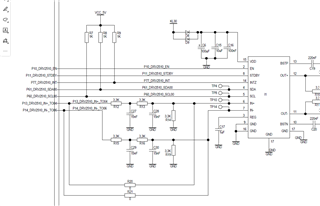
Schematic: 

Thanks!

Ethan Wen

  • Hi Ethan,

    Could you supply the wave form that you are seeing with the DC offset so I can compare? Also, are you bypassing the LPF? With a PWM signal, the filter should be used per section 4.3 in the EVM user guide. For a differential analog input, an AC coupling capacitor should be added. More information on this can be found in section 8.2.1.4 in the device datasheet.  

    Regards,
    Sydney Northcutt 

  • Hi Sydney, 

    Sorry for the late reply. 

    Customer already solved this issue. This is because they found the GND not connected on the layout side. The footprint not designed correctly. 

    Thanks!

    Ethan Wen