This thread has been locked.

If you have a related question, please click the "Ask a related question" button in the top right corner. The newly created question will be automatically linked to this question.

DRV8434: DRV8432 short circuit issue

Part Number: DRV8434
Other Parts Discussed in Thread: DRV8262, DRV8412

Hello TI FAE,

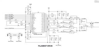
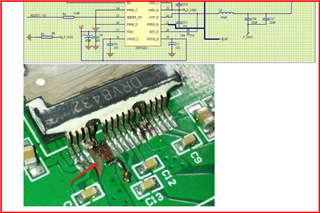
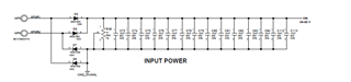
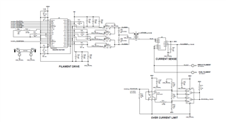
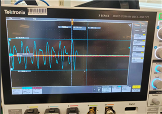
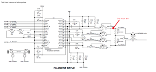
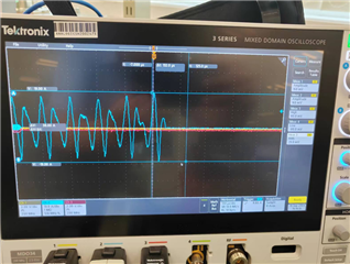
Here we have met DRV8432 short circuit issue on our tank filament board. Detailed schematic is below, also we have a PPT for initial analysis

Tank_Filament_Board_Failure_Analysis_20230909.pptx

  • Hey Eric,

    Thank you for the detailed info, let me look into this.  

    Do you have more bulk capacitance in your system somewhere? I'm adding up around 6x separate 10uF capacitors for 60uF total which isn't a lot. 

    M3,M2,M1 look set up according to Figure 15 in 8.2.2 Parallel Full Bridge Mode Operation. 

    Is this a new design?  The DRV8432 isn't recommended for new designs, so if you're open to looking into new parts I recommend you check out the FAQ I wrote a few weeks ago:  [FAQ] What are the best alternate devices for DRV8432?  I think the DRV8262 would fit you perfectly.  

    Can you share more info on when this issue occurred?  Was it on first power up after assembly, or was it when running a motor at high currents or stall?  

    Regards,

    Jacob

  • Hi Jacob,

    Thanks for quick feedback. Below I provided more information for your review.

    [Application] The DRV8432 is used to drive filament of X-ray tube, and the chip is used in our tank filament board, surrounded by insulated OIL

    [Application] The DRV8432 we used is in parallel mode

    [Application] The DRV8432 does not directly connect to heat sink, in order to do insulation, we add thermal PAD between DRV8432 and heat sink, 

    [Manufacturing] After PCBA SMT process, tank filament board will be washed by using our aqueous clean process, the resistance of our wash water will be larger than 17Mohm

    [Situation] The issue happened during system test, not the first time power up, you know, first we will do FCT test for tank filament board, then the subsystem test, during subsystem test, we will fill in insulated OIL. After subsystem test, we will put Tank into CT gantry to do X-ray radiation, in this situation, we faced more failure

    [Situation] In more cases, when the issue happened, the DRV8432 will be broken directly, not ok to do more investigation. the PPT I provided, is the only one PCBA that DRV8432 is still functional, but the phase shift of DRB8432 output is not fully 180degree, after we change another chip, the phase shift is back to 180 degree.

    -----------------------------------------------------------------------------------------------------------------------------------------------------------------------------------------------------------

    Also I have more questions below

    1) How about the ESD HBM value of this chip, in datasheet, only shown CDM value ?

    2) Humidity sensitivity ?

    3) Is it ok to go through water clean process ?

    more items will be added later ... 

  • DRV8432 DKD package is what we used, How about the HEAT SLUG connection ?  to the GND internal ?

  • Hi Eric,

    Sorry for late reply here. Let me take some time to review your questions and I'll reply back with an answer asap.

    BR,

    Pablo

  • Any update today ?

  • Hello Eric,

    Filaments of X-ray tubes are similar to incandescent light bulbs whose resistance is very low when not energized (cold). So when the power is applied there will be a very high inrush current almost similar to a short circuit on the load. With a motor load the inductance of the motor does a natural limiting to the rise time of this current. However in this circuit only the series 15uH inductors L1 t o L4 contributes to the inductance that will slow down the current rise time. We need to make sure if that will be enough for this application. See page-13 of the datasheet. It depends on the VIN and the cold resistance of the filament. What is the VIN voltage supplied to the PVDD pins? I am unable see this value in the PPT. Can we get a capture of the current waveform when first time power up is done after the filament is at ambient room temp of the application? Especially we need to look at the current profile during the first 250 ns. We can calculate if the inductors values are sufficient to guarantee safe operation of the driver at first startup of the filament drive if we know the VIN voltage and filament cold resistance. Current rise during Toc_delay or IOCT of 250ns (typ) could be higher than safe limit before the Ioc limit kicks in. If this is not mitigated the driver will be damaged. 

    Looking at the below picture, it appears that pins have been damaged due to excessive current flow. If it was a moisture damage due to washing with water and moisture absorption by the IC package, usually the package gets busted. It doesn't appear to be the case based on this image. I assume proper DI/DM water was used and adequate drying process was followed.  


    Lastly, what is the failure rate? How many boards were tested and how many failed with damaged device? Did the failure happen always with the first power on with the filament connected and driven?

    Regards, Murugavel

  • Till now, at least 5 pieces of DRV8432 failed, not at the first time for sure, the total failure rate is around 15% 

    Below listed the test steps related with DRV8432.

    [Step1] DRV8432 will be soldered on our Tank Filament Board for Function Test in the air, we called PCBA level function test

    [Step2] Install Tank Filament Board into HV Module for subsystem function test, no oil in this step, called subsystem function test

    [Step3] Fill in insulation oil into HV Module, then put this HV Module into CT gantry with X-ray tube and rotation, called system test, 5 pieces failed at this step

    Total capacitors for VIN is about 16 pieces of 10uF, about 160uF, due to the PCB dimension, these are the maximum capacitors we can used for VIN of DRV8432.

    Power input schematic


    DRV8432 peripheral circuit

    For inrush current, I will do measurement later this week and check if serial inductances are enough or not ?

    For DRV8412 has different PCB footprint with DRV8432, right ? Do TI has the same PCB footprint IC for DRV8432 replacement ?

  • Hi Eric,

    Thanks for the update. Looks like failure had happened in step 3 only, correct? "Fill in insulation oil into HV Module, then put this HV Module into CT gantry with X-ray tube and rotation, called system test, 5 pieces failed at this step".

    Understood about using 16x 10uF capacitors for VIN. Should be okay. Yes, looking at inrush current in Step2 vs. Step3 might help us with a clue. Thanks..

    Based on the schematic I see an external current sensor and over current limiter. How does the over current limiter limit the current? What is the response time?

    "For DRV8412 has different PCB footprint with DRV8432, right ? Do TI has the same PCB footprint IC for DRV8432 replacement ?". Not the same footprint. This product also has integrated current sensor with analog output IPROPI for external use.

    Regards, Murugavel 

  • During inrush test, I have captured below waves, which is under load unconnected, the PID loop control the output to maximum current for several seconds, the maximum current is about 19A with PWM A& B in parallel mode.


    Is OC_ADJ pin aimed to limit the output current ? I would like to limit output current.

    For inrush current, i try to measure many times, no larger current. 

  • Eric,

    Is OC_ADJ pin aimed to limit the output current ? I would like to limit output current.

    The OC_ADJ is for setting the overcurrent threshold. Section 7.3.2.2 of the datasheet provides more information on the various OC protection modes.

    For inrush current, i try to measure many times, no larger current.

    It is hard to tell due to the time scale. Are the 16A spikes occurring for less than 250ns? Can you provide a zoomed in waveform?

    Regards,

    Pablo

  • Zoomed waves have been uploaded below.

    As you known, we have used thermal pad between DRV8432 hot slug and heat sink in the current design. now we have removed the thermal pad and directly installed heat sink on DRV8432 with optimized stand off height, once this Tank filament board put into oil, it will have much better thermal dissipation.

    For over current risk, we will limit PWM duty cycle to avoid any over current risk, the firmware is under coding now

  • Hi Eric,

    Yes you'll have to limit the overcurrent especially for the resistive load of this application to avoid damaging the device. Let us know how the firmware update goes. Thanks.

    Regards, Murugavel