This thread has been locked.

If you have a related question, please click the "Ask a related question" button in the top right corner. The newly created question will be automatically linked to this question.

DRV8876-Q1: Current Chopping nFAULT Detection

Part Number: DRV8876-Q1

Dear, Support team.

Our customers are evaluating the DRV8876-Q1.

Target function: Relationship between “current chopping mode” and “overcurrent protection (OCP)”
In current chopping mode, the H-bridge transitions to braking when the ITRIP threshold is exceeded;
We recognize this as a function to reduce motor current consumption.
Overcurrent protection (OCP) disables all MOSFETs in the H-bridge when the overcurrent threshold IOCP is exceeded.
There is a possibility that it will be done.
In the customer's circuit design, the relationship is ITRIP threshold < overcurrent threshold IOCP.
Current chopping mode operates before overcurrent protection.

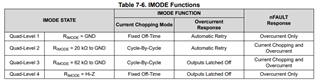
I want the microcontroller to detect the low output from the nFAULT pin when overcurrent is detected using IMODE Functions' "Quad Level 4".

The customer's usage is that the current chopping threshold is lower than the overcurrent threshold, so current chopping reduces current consumption.
Will the overcurrent threshold be reached?
(Will the microcontroller not be able to detect the low output from nFAULT when overcurrent is detected?)

Is it possible that the overcurrent protection does not work due to current chopping mode?
Overcurrent Threshold Any attempt to generate a current that exceeds the IOCP is suppressed by the current chopping mode.
Is there a possibility that overcurrent cannot be detected?

To give you specific numbers, the motor current consumption is
・If it exceeds 3.1A: Current chopping operates.
・If exceeds 3.5A: Short circuit detection operates
I want to have a relationship like that.

Thanks & Best regards,
Hiroaki Yuyama

  • Hi Hiroaki-san,

    The OCP function is generally triggered by in-rush current during motor start-up or stall. The current chopping is done by a set threshold to keep the motor current from exceeding a certain level during normal operation.

    There is an internal blanking time (tBLK) that will ignore current and voltage transients during PWM switching and will make sure current regulation is not entered prematurely.

    The OCP will trigger and disable the FETs and pull nFAULT low when the OCP threshold is exceeded for more then tOCP. 

    It is generally recommended to have a larger gap (3.1A and 3.5A) between ITRIP and OCP thresholds but as long as the OCP threshold is exceeded for tOCP the overcurrent threshold will trigger. 

    Best,

    David

  • Hi David-san,
    Thank you for your advice.

    We will set the threshold by considering the internal blanking time (tBLK) and tOCP time.

    Best regards,
    Hiroaki Yuyama

  • Hi David-san,
    Thank you for your technical support.


    Our customer caused a short circuit between the motors while they were rotating.
    At this time, I checked whether the nFAULT pin for overcurrent detection outputs a low level.
    As a result, due to the current chopping function, the motor current consumption peaked at the chopping threshold, and overcurrent could not be detected.

    DRV8876-Q1 settings and goals
    ・IMODE=Hi-Z quad level 4.
    ・If it exceeds 3.1A: Current chopping operates.
    ・When exceeding MIN3.5A/Typ.5.5A: Short circuit detection operates.
    *The nFAULT pin outputs low upon overcurrent detection.

    The customer's goal is to use a microcontroller to detect the low output of the nFAULT pin during overcurrent detection.
    Due to the current chopping function, overcurrent detection was not possible in the event of a short circuit between motors.

    1. Is there a way to disable the current chopping function?
    2. For example, will it be disabled by setting the Vref terminal open?
    3. What is the purpose/purpose of the current chopping function?
    4. Even if there is a short circuit between the motors, overcurrent cannot be detected due to chopping, so I do not understand the purpose of implementing the chopping function.
    5. If the chopping function cannot be disabled, and nFAULT is output low even with current chopping like in quad level 3, is it not possible to latch nFAULT low after chopping even once? (There was a description that it can be latched to Low in case of overcurrent)

    In the datasheet section 7.3.4.3 OUTx Overcurrent Protection (OCP),
    It says, "In latched off mode, the MOSFETs will remain disabled and nFAULT pin driven low until the device is reset through either the nSLEEP pin or by removing the VM power supply."

    Best regards,
    Hiroaki Yuyama

  • Hi Hiroaki-san,

    The current regulation can be disabled by connecting the IPROPI pin to GND and setting VREF higher than GND.

    A screen shot from the datasheet section 7.3.3.2 will provide more information on current regulation.

    This should allow the OCP threshold to be detected without the dampening from current chopping.

    Best,

    David

  • Hi David-san,
    Thank you for your Answer.

    We will check the customer's IPROPI pin settings, and VREF and OCP threshold.

    Best regards,
    Hiroaki Yuyama

  • Hi David-san,
    I have an additional question.

    Is it possible to insert a brushed DC motor's noise killer capacitor between OUT and GND?
    If so, is there an upper limit for capacitor capacity?
    Also, when I inserted a capacitor in parallel with the motor, an overcurrent flowed.

    Best regards,
    Hiroaki Yuyama

  • Hi Hiroaki-san, 

    Yes, capacitors can be placed at the output. It can be done by placing a capacitor between OUT and GND or between OUT1 and OUT2. 

    In order to protect the driver from any high frequency noise elsewhere in the circuit, a capacitor is placed between OUT and GND. 

    Placing a capacitor between OUT1 and OUT2 close to the output pins will protect against any switching noise generated from the driver. 

    For more information on input and output capacitors please see the application note attached below (section 2 for output capacitors):

    https://www.ti.com/lit/an/slta055/slta055.pdf 

    Best,

    David

  • Hi David-san,
    Thank you for your advice.

    We asked the customer to refer to SLTA055 for the capacitor capacity of OUT1 and OUT2 of DRV8876-Q1.
    However, the customer read the capacitor capacitance caution for Switching Regulators. Does the same caution apply to motor driver DRV8876-Q1?

    I understand that the switching structure of MOS FETs is the same.
    Do you have any suggestions to persuade customers that motor drivers are the same?


    Best regards,
    Hiroaki Yuyama

  • Hi Hiroaki-san,

    Yes, the selection of a capacitor will be the same. The parameters required for the reduction of ripple voltage do not change. This application note has proven successful for many motor drive capacitor calculations in the past.

    Best,

    David

  • Hi David-san,
    Thank you for your Advice.

    We make sure our customers understand that Switching regulators and Motor drivers have the same FET ON/OFF mechanism.

    Thanks & Best regards,
    Hiroaki Yuyama