Other Parts Discussed in Thread: C2000WARE
Hi,
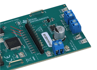
I'm trying to communicate via SPI using the F28379D dev kit with the DRV8434S, I'm using a carrier board with the following connections between F28379 and DRV8434S:
SPIA SOMI -> SDO
SPIA SIMO -> SDI
SPIA CLK -> SCLK
SPIA CS -> SCS
For example, reading one of the register parameters which includes both transmission and reception.
Looking at the libraries and documentation this is what I think comes close to a solution, but unfortunately it doesn't work.
First of all I initialize the SPI GPIOs:
void configGPIOs(void)
{
    //
    // GPIO59 is the SPISOMIA.
    //
    GPIO_setMasterCore(59, GPIO_CORE_CPU1);
    GPIO_setPinConfig(GPIO_59_SPISOMIA);
    GPIO_setPadConfig(59, GPIO_PIN_TYPE_PULLUP);
    GPIO_setQualificationMode(59, GPIO_QUAL_ASYNC);

    //
    // GPIO58 is the SPISIMOA clock pin.
    //
    GPIO_setMasterCore(58, GPIO_CORE_CPU1);
    GPIO_setPinConfig(GPIO_58_SPISIMOA);
    GPIO_setPadConfig(58, GPIO_PIN_TYPE_PULLUP);
    GPIO_setQualificationMode(58, GPIO_QUAL_ASYNC);

    //
    // GPIO61 is the SPISTEA.
    //
    GPIO_setMasterCore(61, GPIO_CORE_CPU1);
    GPIO_setPinConfig(GPIO_61_SPISTEA);
    GPIO_setPadConfig(61, GPIO_PIN_TYPE_PULLUP);
    GPIO_setQualificationMode(61, GPIO_QUAL_ASYNC);

    //
    // GPIO60 is the SPICLKA.
    //
    GPIO_setMasterCore(60, GPIO_CORE_CPU1);
    GPIO_setPinConfig(GPIO_60_SPICLKA);
    GPIO_setPadConfig(60, GPIO_PIN_TYPE_PULLUP);
    GPIO_setQualificationMode(60, GPIO_QUAL_ASYNC);
}
I configure the controller's SPI as master:
void initSPIAMaster(void)
{
    //
    // Must put SPI into reset before configuring it
    //
    SPI_disableModule(SPIA_BASE);

    //
    // SPI configuration. Use a 500kHz SPICLK and 8-bit word size.
    //
    SPI_setConfig(SPIA_BASE, DEVICE_LSPCLK_FREQ, SPI_PROT_POL0PHA0,
                  SPI_MODE_MASTER, 500000, 8);
    SPI_disableLoopback(SPIA_BASE);
    SPI_setEmulationMode(SPIA_BASE, SPI_EMULATION_FREE_RUN);
    SPI_setPTESignalPolarity(SPIA_BASE, SPI_PTE_ACTIVE_LOW);
    //
    // Configuration complete. Enable the module.
    //
    SPI_enableModule(SPIA_BASE);
}
I build and send the packet checking that the value received is the expected one:
volatile uint8_t reg_value = 0;
reg_value |= 0x4000;                       // Set R/W bit
reg_value |= ((0X05 << 9) & 0x3F00); // Configure register address value (CTRL3)
reg_value = (uint8_t)((reg_value>>8) & 0xFF);
volatile uint8_t dataMSB   = 0;
volatile uint8_t dataLSB    = 0;

SPI_enableModule(SPIA_BASE);
// send first byte
SPI_writeDataNonBlocking(SPIA_BASE, reg_value<<8);
// wait transmission end
while(SPI_isBusy(SPIA_BASE));
// read first byte
dataMSB = (uint8_t)SPI_readDataNonBlocking(SPIA_BASE);
// send second byte
SPI_writeDataNonBlocking(SPIA_BASE, 0x00);
// wait transmission end
while(SPI_isBusy(SPIA_BASE));
// read second byte
dataLSB = (uint8_t)SPI_readDataNonBlocking(SPIA_BASE);
// reset SPI
SPI_disableModule(SPIA_BASE);
rData = ((((dataMSB<<8) | dataLSB) & 0x00FF)>>0x0); // complete data
// Check received data against expected data
if(rData != 0x06) // ctrl3 default value on power on
{
    // Something went wrong. rData doesn't contain expected data.
    ESTOP0;
}
I always get 0 even when changing the CTRL address. They don't seem to communicate. Where am I doing wrong? Is it possible to have a working example of communication between the two devices?
Thank you,
Biagio