This thread has been locked.

If you have a related question, please click the "Ask a related question" button in the top right corner. The newly created question will be automatically linked to this question.

DRV8462: Loses step and stalls in proximity to the stepper motor

Part Number: DRV8462
Other Parts Discussed in Thread: , DRV8962

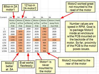
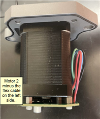
I have a circuit (uP, driver, supply) staged on the backside of a NEMA 17 stepper (120oz-in, 2A, 3.9mH, 48VDC).  I notice when we separate the pcb away from the motor by extending the phase wiring, we're able to step/microstep up to 1500rpm.  When we mount the pcb on the backside of the motor (to utilize a rear magnet for encoder) we see that we start losing step and stall rather quickly (its better at full step but gets worse as we start cutting the step rate).  It appears we're running into some EMI/noise.  What are some go-to items that you would check that are in place?  Or better yet, who has ran into this scenario and what was your solution?  Thanks much in advance, this forum is great.

  • Hi Chris,

    Thanks for contacting us via this forum. I have a NEMA-17 stepper motor with me. I tried to reproduce your problem by placing the motor while running it with 16 usteps, 48V VM supply, 2A IFS with our EVM and placed the motor base on the bottom side of the EVM right underneath the driver IC with a paper thin insulating material. I moved the motor around the driver area as well as the microcontroller area. I was unable to detect any anomaly with the motor drive, no missed steps. I did not ground connect the motor body but it would be good practice to do it. I have not heard about a similar scenario.

    How was the PCB mounted on the motor? Would it be possible the mounting caused a mechanical stress to the motor housing or shaft increasing the friction? Do you have capacitors on OUTA1,A2 and B1,B2 terminal connections - this can reduce EMI since you suspect EMI related issue.

    It would be helpful to look at STEP input waveform, out current waveforms unmounted and mounted and compare. If you could capture these by triggering at these missing pulses areas and share with us we can take a look at it.

    Regards, Murugavel

  • well, i think i may have some images to share relating to back emf perhaps..
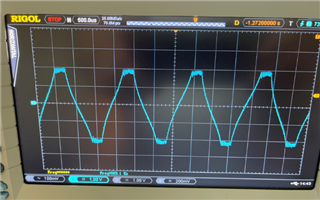
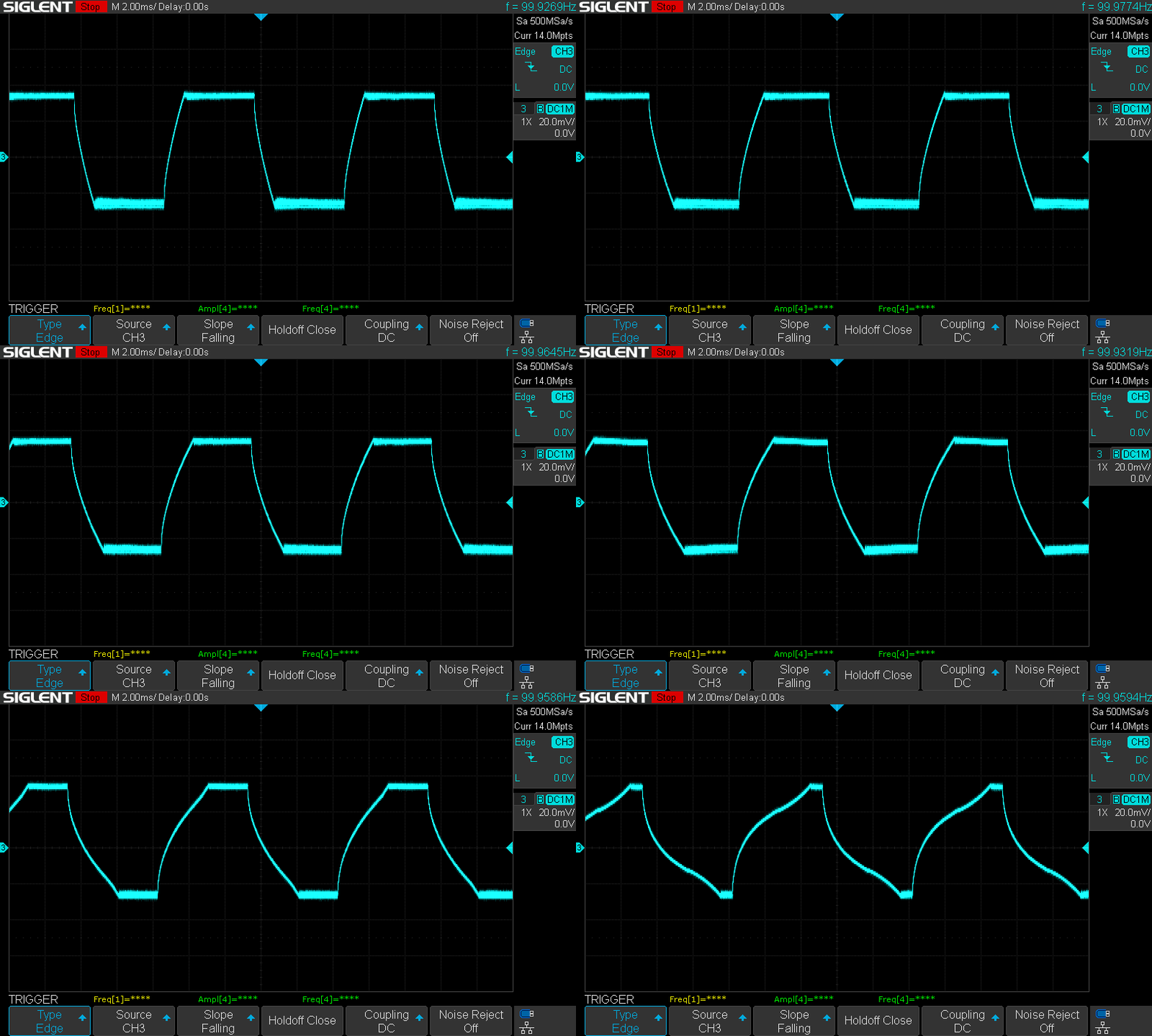
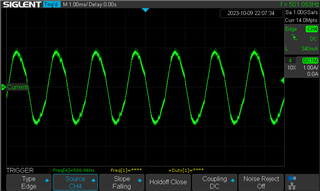
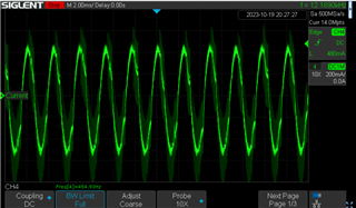
     prior to stall, reaching current level
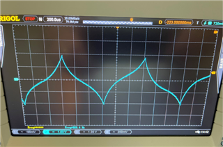
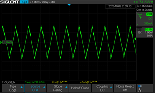
      starting to get close, is current being reached by driver?
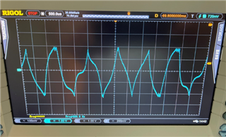
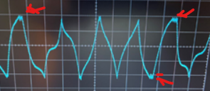
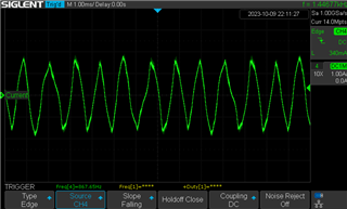
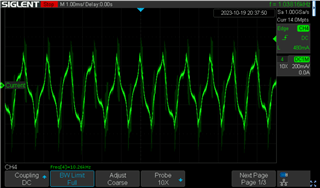
     starting to get wonky when decay mode starts to shift (?)
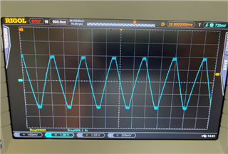
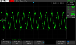
     aaand we're stalled.

    it's in default decay mode.  we tried using another but it still stalls with this particular motor.  

    both the 123oz-in motor as well as the 60oz-in motor we tried have the same characteristics where it seems rather "gravely" at certain points of the motion (0-2000rpm).  in the lesser motor it didn't seem as rough or "gravely".  i'm sure it has to do with the resonance of the motor but the motion isn't that smooth at the step rate given (1/256).  prior to stall, it seems like the decay mode shifts...is that smt the driver does?

    i'll leave it at that and see what thoughts are and next steps.  thank you so much!

  • Hey Chris,

    Thank you for the images!

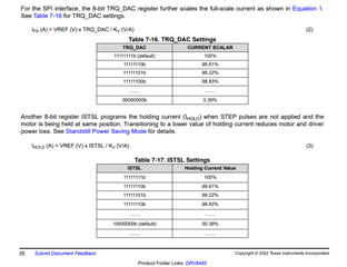
    What is your VREF or Torque DAC setting? These waveforms look to me like the current setting is too high.  The unloaded condition should look like a perfect sine wave if you're in 1/256 microstepping.  Try lowering your VREF voltage or Torque DAC setting until you get a clean Sine wave for the current waveform when unloaded.  It's common to think "More current more better" but more current can actually cause issues.  (Conversely, if you already have a low VREF and Torque DAC, try increasing them).

    Are you using external voltage for VREF or using the internal VREF? 

    Regards,

    Jacob 

  • Hi Jacob, 

    our VREF is set to 2A full scale.  Our Torque DAC setting is 1000 or 100%.  and that makes sense about more current the worse it is because we see it stall sooner when we raise current.  

    when comparing phase current between our pcb and the eval board, we see the current amplitude lower with the eval board as it increases in speed.  when we run ours, the amplitude roughly stays the same (from 0rpm) and it "maybe" lowers a bit right before stall.  we've tried both internal and external VREF.

  • when lowering the DAC to 20%/200mA it will run up to 2000rpm in full step but finer step rates will not.  it progressively gets worse the smaller step rate you go, even automicrostepping won't help.  

    Our acceleration profile is not as smooth as the eval board tho.  it has me wonder if our profile is correct.  

  • Hi Chris,

    The problem you are experiencing is so called midrange instability caused by motor BEMF and inductance. Driver has problems to keep motor current because motor BEMF is close to VM voltage. New drivers are getting better and better at dealing with that phenomena with new decay modes but I think it is still a problem. There a few ways you can deal with it:

    - increase VM voltage, (full step is better than microstepping because its RMS motor voltage is higher)

    - find a motor that has lower inductance and higher current, 

    - avoid area of midrange instability by passing that region by fast accelerating, then you will go into speed area where motor current is sinusoidal and controlled also by its BEMF. You will need some large VM cap. to absorb breaking energy when motor stalls at those speeds, otherwise VM voltage spike will cause destruction of the driver. Speed above midrange instability bring its own type of resonance but is a bit easier to deal with.

    - play with driver settings like decay modes, motor current

    - go for BLDC motors that are better suited for such high speeds

    - when you operate stepper motors above lets above 1000rpm for a longer time, please monitor motor temperature, its temperature will rise because of iron losses

    - use viscous dumpers ( I did not tried myself)

    In speed area of midrange instability even small things like motor position, motor load, motor mounting, belt tension etc. can make a difference between motor working and stalling.

    The second picture from top shows current when motor still should work stable with low torque, problems starts at speeds just a bit higher. 

    Regards.

    Grzegorz

  • i appreciate the response Grzegorz.  what i'm a little baffled with is that the TI DRV8462 EVAL board runs this motor at 48v/2A at the speed and step rate that our pcb will not.  ...and when looking at the phase current it looks like the eval board is handling (or it's just an outcome i suppose) the driving of that motor differently.  i'm kinda stumped atm...

  • Hi Chris,

    I think I would start with comparing drivers settings, then drivers diagrams and took a look at pcb layout.

    As I said before even small details can decide if motor runs or stalls in midrange instability area. I try not not operate stepper motors in that area myself, I operate them at speeds lower or higher than midrange instability region.

    Regards,

    Grzegorz

  • Hi Chris,

    Thanks for sharing the waveforms. At 256 uSteps I do not expect much resonance related issues. However the waveforms you shared, especially #1 and #4 suggest they was captured in full-step mode, not in a micro-step mode. Please confirm. 

    The current waveform #2 was at the safe speed where the current barely reaches the target IFS because the VM supply voltage is insufficient to overcome the back EMF and able to push the required IFS at that speed. There was sufficient torque generated to allow the motor overcome all mechanical losses and continue spinning stable. At the speed where waveform #3 was captured the motor barely generated enough torque to overcome the mechanical losses and started skipping steps. Whenever motor skipped a step (temporary stall) the back EMF went low and current regulation cycles appeared..


    Eventually the motor stalled as it could not generate enough torque to sustain rotation. The back EMF dropped to zero and you got waveform #4. 

    All these are expected behavior of a stepper motor driver at full-steps. To achieve higher speeds the VM must be increased to a level to overcome back EMF at the top speed and be able to pump the target current into the motor windings.

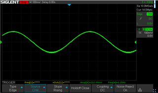
    Here's an example current waveform with 256 uSteps.

    Regarding decay modes, the default decay mode STRC (ripple control) uses mostly slow decay and fast decay whenever necessary, for example during falling currents 3 & 5 quadrants of the current waveform. STDD (dynamic decay) uses mixed decay by finding the suitable ratio of slow and fast automatically. You could choose slow decay mode only or mixed decay modes and avoid the automatic Smart Tune decay modes if you would want to. 

    Also to follow up with you, about your original post, there was a performance difference between mounting the driver to the stepper motor vs. having it away. So were the waveforms you shared related to that? Are there comparison waveforms for the same speed with driver mounted to the motor vs. having the PCB away from the motor?

    Thanks.

    Regards, Murugavel

  • And to add further, Grzegorz's points in his first response are good suggestions. 

    You also mentioned "Our acceleration profile is not as smooth as the eval board tho.  it has me wonder if our profile is correct.". While accelerating to high step rates acceleration profile does matter as well. Faster jumps to higher step rates could lead to early stalling vs. smoother acceleration profile.  

    As well as you said "what i'm a little baffled with is that the TI DRV8462 EVAL board runs this motor at 48v/2A at the speed and step rate that our pcb will not.  ...and when looking at the phase current it looks like the eval board is handling (or it's just an outcome i suppose) the driving of that motor differently.  i'm kinda stumped atm..." . I'd expect the same performance as well under the same operating conditions. You could take the STEP pulses from the EVM header and connect it to your driver board to see if the EVM ramp profile alleviates your issues. 

    Regards, Murugavel

  • Hi everyone, thank you again for this help...it's greatly appreciated!

    To correct some confusion, yes the 4 waveforms that were posted above were in "full step".  Apologies for that.  

    I will get more waveforms posted here shortly and have clear detail to the test scenario.  I'd like to measure this back-emf that's been spoken of and if anyone has a better way to capture that I'd be obliged to hear. Is there a way that I can witness us reaching our VM as we reach higher RPM?   And if it does help, I can post our test results of rpm/current/step-rate between the compared motors.

    Regarding auto-torque, would anyone let us know how ATQ_LRN_MIN_CURRENT, ATQ_TRQ_DAC, ATQ_TRQ_MIN and ATQ_TRQ_MAX relates to TRQ_DAC?  

    Thanks again.  

    *(top-right yellow text box) ...to the "rear" of the motor

  • Hi Chris,

    " I'd like to measure this back-emf that's been spoken of"

    - Disconnect motor from driver,

    - Connect one motor winding to oscilloscope probe

    - Turn motor shaft with fingers and try to record voltage sinusoid at its max. amplitude

    - Read sinusoid amplitude and its period, then you can calculate BEMF in Vrms/rpm, Vmax./rpm or in any other units

    - To propel motor shaft you can also use some battery drill at lets say no more than 500rpm, be careful with oscilloscope probe settings, voltage can exceed 100V!, be careful not to get electrocuted and with using drill itself.

    Regards,

    Grzegorz

  • In looking at AC voltage across one of the phases, I see close to rail voltage (48V peak) around 1200RPM.  I did use a drill to spin the shaft.  Thoughts on that tidbit?  I'll also try to get our powder brake connected to the motor and do some testing with a load on the shaft...as all other test results were done with an unloaded shaft.

  • Hi Chris,

    Thanks for the clarification. This application note will be helpful to understand the auto-torque parameters you mentioned, https://www.ti.com/lit/an/slvaff1/slvaff1.pdf

    When auto-torque is disabled TRQ_DAC scales the IFS as described in the datasheet. With auto-torque enabled TRQ_DAC is ignored and ATQ_TRQ_DAC takes over the current scaling. The maximum value of the IFS is determined by VREF voltage. When the STEP pulses are not input the ISTSL settings take precedence regardless of auto-torque status.   


    You mentioned "Is there a way that I can witness us reaching our VM as we reach higher RPM?". When the output HS FET is turned on the OUT terminal voltage will immediately reach VM. However it may or may not be sufficient to let the winding current reach its target IFS within the step period or microstep period. As the motor speed increases the available voltage across A or B phase coils would be VM-VBEMF. See below GIF demonstrating how IFS rise time changes with reduced VM voltage at a constant stepping speed. The narrowest peak was at 6V and widest at 16V for the motor that was tested. . 


    Regards, Murugavel

  • Hi Chris,

    Like I mentioned in my last post a couple of minutes ago, the effective voltage available across the windings will be VM-VBEMF. You mentioned "In looking at AC voltage across one of the phases, I see close to rail voltage (48V peak) around 1200RPM.  I did use a drill to spin the shaft.  Thoughts on that tidbit?  I'll also try to get our powder brake connected to the motor and do some testing with a load on the shaft...as all other test results were done with an unloaded shaft.". This tells me at 1200 RPM you would not have sufficient potential difference across the A or B coils for the desired current flow. For this motor if you'd want the motor to run at 1200 RPM you want to increase the VM voltage high enough to have VM-VBEMF to be able to drive the target current through the winding well within a step or microstep period to achieve a clean waveform and usable torque from the motor. The DRV8462 can support a maximum VM supply of 65V. BEMF is proportional to the speed of the motor, regardless of the load condition. Output torque generated by the motor is proportional to its winding current during the entire step or microstep. When you load the motor its stalling speed would be lesser than the stalling speed unloaded for the same VM supply voltage.  

    Regards, Murugavel

  • Thank you Murugavel4637 for the input,

    we'll look further into the detail you explained.  

    i'll place a couple more images on this thread to help show our scenario we're dealing with: 

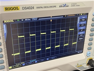
     This is the step pin when Motor2 is inside the enclosure.
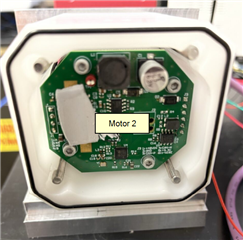
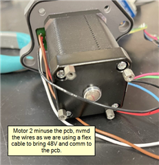
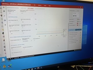
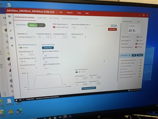
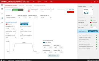
    Also, we're having difficulty getting the "auto-torque" to work on the eval board.  we've watched the demo vid on TI's site showing how it's supposed to work but we don't see the current reduce/increase with load. Here are our settings: 

    thank you all.

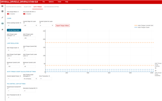
  • Thanks Chris for the images. It gives us a better understanding of your setup. Based on the GUI screen capture it appears you have the proportional constant KP = 0. It must be 1 or higher, for most use cases 1 will be fine for the auto-torque closed loop to function. 

    Your current setting is 2A, auto-torque min current is 10. This will definitely stall the motor. You have to identify the minimum current your system will operate without stalling and based on that calculate the min current value input. Examples are in the data sheet and the application note link I provided in one of my previous posts. Please review those and set up auto-torque accordingly. 

    Regards, Murugavel

  • Is the superimposed noise due to oscilloscope grounding issue or something else. Is it much cleaner when the board is outside and away from the motor?

  • Hi Chris,

    "When we mount the pcb on the backside of the motor (to utilize a rear magnet for encoder) we see that we start losing step and stall rather quickly" - I would check if problems occur with and without magnet when pcb is mounted at the back of the motor. Rotating magnet may induce currents in pcb traces that could interfere with your circuit.

    Regards,

    Grzegorz

  • Hi Murugavel,

    To update where we're at, we haven't witnessed test results to confirm that pcb distance from the motor is a constant.  in certain situations, having the pcb next to the motor worked as well as further away.  what i am interested in learning more about is this BackEMF and if anyone has knowledge or experience with "field-weakening"?  ...and, does auto-torque have anything to do with adjusting current to deal with BackEMF?...or would we have to do this on our firmware end to lower current as we reach higher RPM?  Our voltage supply is capped at 48V and so we cannot increase voltage (except for benchtop testing).  we do have a couple different motors coming in tomorrow that are lower inductance.  we'll test those to see a difference of the phase currents (3.9mH vs 2.5mH). 

    aside from BackEMF, we have sniffed around the assembly with a h-field probe and sniffer probe to only find slight emission at a harmonic of our clock...nothing too alarming. 

    we have still not fine tuned the auto-torque feature on either the eval board nor our own pcb.  these are our settings thus far:

    but anyways, i told my team my bet is on BackEMF as our major gremlin.  can anyone confirm/deny this claim?  

    thanks again Murugavel and the rest of the community...this has been some sticky mud we've been stuck here recently. 

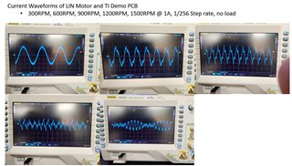
  •  for a reason unknown to us, we lose our current sinewave after 300rpm with the the EVAL board & 3.9uH motor.  (see images below)

    then, when using a smaller torque/inductance motor (1uH) we still struggle to maintain well-regulated current profile. i'll try posting the images in the next reply as the forum doesn't seem to allow inserting additional images.

  • Hi Chris,

    " ...and, does auto-torque have anything to do with adjusting current to deal with BackEMF?...or would we have to do this on our firmware end to lower current as we reach higher RPM? " Auto torque does not deal with adjusting current to deal with back EMF. It increases or decreases the current based on the load torque. You'll have to do that with your firmware to lower current at higher RPM as needed.

    Yes at higher rotational speeds back EMF is one of the major force working against allowing the target current via the windings. In addition the L/R time constant of the motor also plays a role which also calls for higher VM voltage at higher speeds to pump in current fast enough through the winding inductance.

    "for a reason unknown to us, we lose our current sinewave after 300rpm with the the EVAL board & 3.9uH motor." This may be happening for with the motor unloaded especially in STRC decay mode. Can you load the motor and see if the behavior is different or try STDD decay mode?

    Regards, Murugavel

  • Hi Chris,

    While the second set of waveforms look a little abnormal to me for most part it is expected behavior of a stepper motor spinning at high RPM and even with no load at some high speed the motor will stall because it cannot generate enough torque.

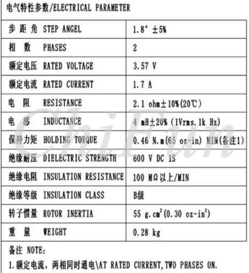
    See below my quick check with a NEMA17 stepper with the following specifications. I used 48V and set IFS to 1.8A. 256 uSteps. 

    Here are the current waveforms I captured. Decay mode was set to STDD. No load.

    600 RPM:

    900 RPM:

    1000 RPM:

    1200 RPM the motor stalled. This is expected behavior. We can squeeze some more speed if we increased the VM supply to 60V. I did not have a 60V supply. The DRV8462 can support up to 65V. I hope this helps.

    Regards, Murugavel

  • Hi Murugavel, 

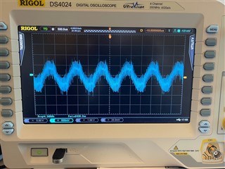
    thanks for the feedback.  we did switch to the STDD decay mode and that was improved performance.  although, i was only able to reach approximately 1000rpm while still having what represents a phase current sine wave.  i did have to reduce current as the motor was ramping in speed, as you stated.  (see image)  the waveform in the image appears very noisy and i'm not certain if that's real or coupled noise.  ..this is using the eval board and a 2.5uH motor. 

      our setup @256 step, .5A, 1000rpm
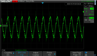
    and so i'm left with the question of how is one to achieve the speed the motor is capable of?  (this motor is spec'd to 2000rpm)

    with our project, we're tasked to achieve performance of a smart motor we're currently using [256 step, 2000rpm, 60+oz-in torque].  from what we're finding after designing around 2 different drivers is that this may be a tougher feat than originally thought.  our purchased smart motor keeps a very clean sine wave throughout it's rpm range (1-2000rpm @256 step).  as well, when tearing down the motor assembly it appears to be mostly discrete components with perhaps some asic devices.  

     purchased smart motor phase currents at speed.  as you see their regulated current at 2000rpm is quite cleaner than what we've been able to produce. 

     purchased smart motor's measured torque on our dyno (not certain for the rise at 1700rpm), although it does resemble what they spec on their torque chart at 48VDC.

    can anyone offer suggestion if attaining this type of torque graph (above) is possible with this DRV8462 driver?  thank much, i appreciate the help with this.

  • Hi Chris,

    If I wanted to do this the easy way I would try the motor below (it has around 70 oz-in of torque) or any other with similar small winding inductance.

    https://en.nanotec.com/products/375-st4118l3004-a

    If you need lets say 100 motors or more you can ask motor manufacturer for a motor with custom windings later.

    I would try then to use first nominal motor current settings with full step and microstep and check the motor max. speed where problems began.

    With motors at 3A or more you will get some heat from DRV8462 but you can try to use Autotorque to minimize it.

    You may be interested in thread below

    https://www.cnczone.com/forums/stepper-motors-drives/13678-effect-microstepping-torque.html

    Regards,

    Grzegorz

  • Hi Grzegorz, 

    your recommendation is a good one as that's the "lower inductance" motor i speak of.  we ordered that one as well as ST4118D3004-A in for demo.  we still struggle in driving these motors past 1000rpm where we still have some measurable torque and no stall.  when we use auto-torque, it does lower current and tries to maintain a sine wave but i'm uncertain if/how we're to 'create a reference table of sorts' to adjust settings as the speed increases?  would someone be willing to describe how they set/adjust for auto-torque at various speeds?  

    and in reference to the purchased motor we're comparing against, i would like to know if someone sees this driver being a suitable component to get there (2000rpm at 1/16th step or greater).  

    and just a idea but what are people's thoughts about using a lesser voltage motor (36VDC) and during peak RPM demand to up the voltage to 48V and lower current as needed to stay within parameters?  i'm trying to mitigate back-emf buildup.  

    thanks. 

  • Hi Chris,

    Did you try to run ST4118L3004-A/B at 48V, full step with DRV8462 current set to around 3A? By the look of ST4118L3004-A/B torque/speed characteristic I would expect that motor to be able to run somewhere around 2000rpm without going into midrange instability area.

    Regards,

    Grzegorz

  • Hi Chris,

    The below capture looks much noisy than expected. What was the TOFF setting in the STDD mode? Were you able to make sure it was not coupled noise? It might be useful look at one half cycle by using a faster time scale. What's the part# for the NEMA17 motor that you tested? Is it available off the shelf or a custom motor? 

    You mentioned "our purchased smart motor keeps a very clean sine wave throughout it's rpm range (1-2000rpm @256 step)". What is the part# for this smart motor? Does it have a voltage boost circuit?  .

    Regards, Murugavel

  • Hi Murugavel, TOFF was in default position as we didn't change the setting.  we tried others but did not fair better.

    Here are some better waveform captures: (LIN motor link)

    (below, Nanotec link)

    (below, Shnieder/Novanta LMD17, pdf below)

    LMD17_CAN_2018.2.pdf

    Schieder's circuitry looks to be custom and discrete components.

  • Hi Chris,

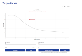
    Thanks for sharing the information. According to the datasheets the LIN motor will not  provide enough torque at 1200 RPM at 48V and 2A (specified current). See below.

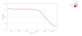
    Whereas the Nanotec motor will give you better performance at 1200RPM according to their datasheet at 48V, 3A. See below. Often times these curves are for either full-step or half-step modes. At higher microsteps there will be a reduction in torque output. Some vendors provide this information, some don't.

    Regards, Murugavel 

  • Perhaps, what my question really is...can this TI driver achieve phase current results similar/same to what the last image shows?  Now, I can get a custom motor spec'd but I'm needing to understand if this driver can regulate the current well enough to move forward in my project.  Long term, I'd like to be able to control this motor using FOC.  Would you see this possible with the DRV8462 or would I have go another route in your (or another's) opinion?

    Thanks.

  • Hi Chris,

    The current waveforms could differ due to differences in the decay modes used but if the motor is capable of delivering the necessary torque at the target velocity with the given supply voltage and target, IFS it should spin with high RPM in the range you highlighted. I have a NEMA17 Moons' stepper with me, https://www.moonsindustries.com/p/am-series-standard-hybrid-stepper-motors/am17hdb410-01n-000004611110011162. I connected this to the DRV8462EVM with the following settings. VM = 48V, IFS = 0.5A, 256 uSteps, STDD decay mode with default TOFF and no load. Below are the current waveforms at 500RPM, 1000RPM and 2000RPM. The EVM GUI cannot generate higher than 65535PPS. So I removed the jumper short for the STEP input at the header and input 3V external STEP input with a linear ramp for acceleration. Linear ramp acceleration is critical to achieve higher speeds else inertia will stall the motor.

    500 RPM:

    1000 RPM: (loading the stepper improves this waveform)

    2000 RPM:

    I could consistently run the motor at 2000 RPM with no issues. Whether you'd be able to achieve the same depends on your motor characteristics and acceleration profile. The DRV8462 is capable of driving the stepper I used for this test all the way to 2000 RPM with no issues. I did notice a resonance behavior around 1330 RPM which resulted in lower current amplitude but still generated enough torque. The reason for this is the back EMF amplitude and phase beating with the drive current waveform. When I loaded the motor there was improvement with this waveform at these specific speeds. 

    Like you mentioned sophisticated FOC type of stepper driver could get you better current waveforms throughout the speed range of your interest. Of course this would involve complex algorithm. For this purpose you should consider a driver device without the internal indexer. DRV8962, quad half-bridge driver would be a good candidate. Please refer to this E2E post, https://e2e.ti.com/support/motor-drivers-group/motor-drivers/f/motor-drivers-forum/1250105/closed-loop-stepper-driver?tisearch=e2e-sitesearch&keymatch=DRV8962%2525252525252520stepper%2525252525252520motor%2525252525252520field%2525252525252520oriented%2525252525252520control#.

    I hope this helps. Thank you.

    Regards, Murugavel   

  • Hi Murugavel, 

    Thanks for putting this last reply together, that helps to see another eval board run these waveforms (insert Roger Bannister effect).  With our prior testing, we've always run full-step (6667pps) and then used auto-microstepping 1/256 to perform 256 step rate @2000RPM.  Is there a performance difference in using auto-microstepping vs running a very fast step rate into the STEP input?  I believe we came across a max spec for 100Khz input to the STEP pin.  Would you mind further describing your setup for running 256uStep?

    I'm looking into the DRV8962 and have an eval board on the way, thanks for that lead.  if that allows for greater current control at a finer individual increment, i believe that's what we're looking for.  ideally, we'd like a driver that would handle the current feedback and run the PID loop based on our STEP input..but perhaps that's too much to ask for in a packaged driver?  for the DRV8962 it looks to also be new and i don't see anyone having stock.  we'll demo based on stock being fulfilled soon.

    Regarding your comment on 'loading' to improve the waveform, was that in code or mechanical load?

    Thanks again Murugavel.  You've been instrumental with your responses.

  • Hi Chris,

    You're welcome. You're correct. The maximum spec for fstep is indeed 100 kHz. You said "With our prior testing, we've always run full-step (6667pps) and then used auto-microstepping 1/256 to perform 256 step rate @2000RPM.". Yes this is correct approach. "Is there a performance difference in using auto-microstepping vs running a very fast step rate into the STEP input?". Performance will be identical.

    As I had the previous setup still at my lab I ran the EVM with the GUI settings as per the below screen shot. STDD decay mode was used. The performance was identical to my previous experiment.


    Here's the current waveform at 2000 RPM. 

    I hope you'll be able to work on your PID algorithm with the DRV8962. Yes these are recently released products. "Regarding your comment on 'loading' to improve the waveform, was that in code or mechanical load?". I referred to mechanical load.

    Could you please mark this post as resolved at your end? For future queries you can always post a new question with suitable subject title. I'm hoping the discussions we had in this post will be useful several other users of this forum. Thanks!

    Regards, Murugavel