This thread has been locked.

If you have a related question, please click the "Ask a related question" button in the top right corner. The newly created question will be automatically linked to this question.

MCF8315A: Simple position control with BLDC

Part Number: MCF8315A
Other Parts Discussed in Thread: MCT8316Z, MCF8316A, MCT8316A

Hello,

I am looking at MCF8315A for a potential application which requires position control. Can this part do it, provided the motor has three hall sensors built-in?

What I am struggling to understand is how the current position can be extracted and interpreted from the driver, and how to set where I want it to be.

Can someone help me out a bit on that, please? Thank you in advance

  • Hi Konstantin,

    I will aim to provide an answer by next Thursday at the latest.

    Regards,

    Joshua

  • Thank you. Looking forward to your answer

  • Hi Konstantin,

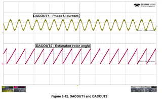
    The MCF8315A can output the estimated rotor angle using a DACOUT pin, see section 8.2.2.7 of the datasheet for more information on this. If you set a DACOUT pin to output the estimated rotor angle that pin will generate a waveform like the one labeled DACOUT2 in Figure 8-12:

    This waveform will rise from 0V to 3.3V as the rotor moves from 0 degrees to 360 degrees. Feeding this signal to an external microcontroller to interpret the angle from the DACOUT signal can then be used to determine the position of the motor. For position control, the MCU can then stop the motor at the desired position using the DRVOFF, BRAKE, or over I2C. 

    Please keep in mind that the accuracy of this method will be limited due to propagation delay and resolution of the DACOUT signal. 

    If your motor has many poles, you maybe able to get higher accuracy position detection using our MCT8316Z device which is a sensored trapezoidal device and can accept hall sensor input.

    For high accuracy current position detection using an encoder will likely be the best option.

    Regards,

    Joshua

  • The DACOUT signal seems like a good way indeed. I will consider that as a possible way to go.
    Also looked also at the suggested MCT8316Z and it is even better with those hall sensor inputs, however, it brought two new questions:

    1. I browsed the datasheet several times and could not see how I can get any information about the current position based on those hall sensors. There is no DAC output either.

    2. There is an interesting ADVANCE input which according to my understanding advances the rotor by a preset degree. Am I right in that interpretation, and if so does that mean every next transition of that input will further advance by the same degree?

    Thank you

  • Hi Konstantin,

    1. I browsed the datasheet several times and could not see how I can get any information about the current position based on those hall sensors. There is no DAC output either.

    The MCT8316Z does not have the DACOUT estimated rotor angle feature present in the MCF8316A.

    Estimating the current position with the MCT8316Z would involve observing the hall sensors output. Please refer to this link for more information on using hall sensors for position sensing: Using BLDC Hall Sensors as Position Encoders.

    2. There is an interesting ADVANCE input which according to my understanding advances the rotor by a preset degree. Am I right in that interpretation, and if so does that mean every next transition of that input will further advance by the same degree?

    The ADVANCE pin is used to advance the phase current by a set degree and will not necessarily advance the angle of the rotor. This setting is similar to the LD_ANGLE setting in the MCT8316A. If you would like a bit more detail on this setting please see section 8.3.11.3 in the MCT8316A's datasheet.

    Regards,

    Joshua

  • Hello Joshua,

    So, I will need to observe the output from the hall sensors, but they are connected to MCT8313Z. Does that mean I have to monitor those links and why are they going into the chip if I can't use them there?

    Understood about the ADVANCE input. Not useful for my needs.

    Thanks

  • Hi Konstantin,

    The the hall sensor input to the MCT8316Z will affect the signal on the FGOUT pin. For the hardware version the FGOUT is fixed to 3x commutation frequency while the SPI variant can set FGOUT to 3x, 1x, 0.5x, or 0.25x the commutation frequency though the FGOUT_SEL register. for the highest position information I recommend using FGOUT in 3x commutation frequency.

    Please refer to section 8.3.15 of the datasheet for information on how the FGOUT signal  relates to the hall sensor inputs.

    Regards,

    Joshua