


Hello Ti Team
I recently constructed a 3-phase inverter circuit (motor driver) using the DRV8350H.
I would like to see how many questions and the design is correct of the DRV8350H.
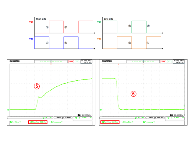
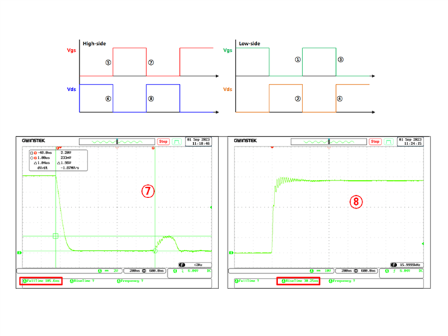
1. It looks slow when I check the waveform of the VGS during the High-Side Turn on.
On the other case, High-Side Turn Off, Low-Side Turn ON/OFF looks fast.
And I can see slow Vgs(high side turn on) waveforms in the provided datasheet.
However, the rise time of Vds looks faster than slow Vgs.
Is this intended Vgs waveform? Is there a reason why only slow high-side vgs turn on?
In addition, according to the Application note (understanding Smart Gate Drive),
the turn on/off time of the Smart Gate Driver series is seen as a time to charge/discharge the current to the Cgd in the Miller region,
not the RISING/FALLING time of the Vgs. I understand it. Is it correct to understand it properly?
2. About four PWM mode.
In my current design, I set the independent mode.
This mode is used in the state where the 3-phase inverter circuit is configured and the high/low-side operates as a complemently.
At this time, the gate driver does not work with the ability to detect overcurrent by measuring voltage of MOSFET Vds?
In a circuit that connects the 3-phase motor load, should I use 6-PWM mode to use overcurrent detection function?
And if I use 6-pwm mode at DRV8350H, the dead time is confirmed to be 100nsec fixed.
If I have more than 100nsec in the MCU when I apply PWM on the gate driver, the fixed dead time of the gate driver is ignored and output is generated?
For example, if the Dead Time of 400nsec is applied in the MCU, the dead time that is finally output from the gate driver is 400nsec (not 500nsec)?
3. I slowly raised IDRIVE and did a work to find the right value.
So it was confirmed that 300mA output (Iep) was optimal.
In 450mA, it was confirmed that the Vgs rose significantly when the MOSFET of the other side was turned on when the Vgs had to be turned off.
It was confirmed that this value rose closer to MOSFET's Vgs(th), and the IDRIVE setting value was not available.
How can I improve this and increase IDRIVE?
MOSFET specifications in use are Vds = 100V, Id = 230A, Cgd = 11.9nC, Vgs(th) = 2.8V
The question is so long... Thanks for reading.
