This thread has been locked.

If you have a related question, please click the "Ask a related question" button in the top right corner. The newly created question will be automatically linked to this question.

DRV8424EVM: DRV8424PWPR Output Current Waveform with respect to Direction Signal

Part Number: DRV8424EVM
Other Parts Discussed in Thread: DRV8424

Hello,

As per the datasheet there is a pull down on the DIR signal?

What would be the current flow direction at the output?

Whether it will be clockwise or anticlockwise?

In the datasheet there is no proper information about the direction signal. Please help me to know the current output direction with respect to direction signal.

  • Hey Guru,

    There is an internal pull-down resistor on the DIR signal.  Check the device datasheet instead of the EVM users guide.

    Therefore the current will follow the reverse of the step sequence in Table 7.4 by default (DIR pin LOW)

    See 7.2 Functional block diagram to also see the resistor location:

    Regards,

    Jacob

  • Hello Jacob,

    current will follow the reverse of the step sequence in Table 7.4 by default. 

    --Can you elaborate on the current flow at the output? Also, if you can let me know if the direction is low the motor movement will be clockwise or anticlockwise?

    Regards,

    Guru Hegde

  • Hey Guru,

    When you send a STEP signal it will go to the previous location in the table.  Let's say you're using 1/2 step, so it will go to spot 8:

    This has -71% current for AOUT current, and per the note "Positive current is defined as current flowing from the xOUT1 pin to the xOUT2 pin while driving."  Therefore current will flow from AOUT2 to AOUT1.  And for BOUT current it is at 71%, so current will flow from BOUT1 to BOUT2.  Hopefully that explains how to interpret the current direction from Table 7-4 for each state.  

    if the direction is low the motor movement will be clockwise or anticlockwise?

    The motor direction will depend on how you connect the 4 winding wires to the motor driver.  Best way to determine that is just by hooking it up and testing it. 

    Regards,

    Jacob 

  • Hello Jacob,

    Thanks for the response. 

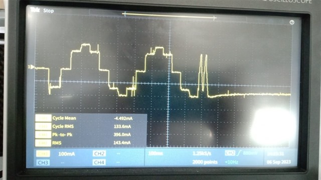
    We have used the allegro motor driver earlier design. Now we replaced that motor driver with DRV8424PWPR. In the earlier motor driver, we got the waveform as attached below. Also attached the waveforms of the new motor driver. It seems to be the direction of the current is reversed. Could you please help me how i can make both the current waveforms as similar. I have verified the measurement set up is same for the test units. Also i measured the current at AOUT2 of DRV8424 the wave form looks same as earlier motor driver waveforms. Please help.

    Older motor Driver Part Number - A3984SLPTR-T

    New motor driver part Number - DRV8424PWPR

    Earlier motor driver(A3984) current waveform 

    New motor Driver waveform.

    Regards,

    Guru Hegde

  • Hey Guru,

    Try setting the Direction to the opposite direction, does that make the output match?

    Also the waveform for the TI part looks a little not-smooth, I recommend trying a different VREF, and try different Decay Modes. 

    Regards,

    Jacob

  • Hello Jacob,

    Try setting the Direction to the opposite direction, does that make the output match -- I will try it out tomorrow.

    The motor driver winding resistance is 60 ohm. Based on that the VREF value I set is 0.264V. Please let me know whether the VREF value is correct or not? I have tried the different decay modes but there is no much improvement. Also wanted to know why there is noise at the 70% of the full scale current?

  • Hey Guru,

    The motor driver winding resistance is 60 ohm. Based on that the VREF value I set is 0.264V. Please let me know whether the VREF value is correct or not? I have tried the different decay modes but there is no much improvement. Also wanted to know why there is noise at the 70% of the full scale current?

    You can try different VREF settings to see if it improves the signal, that seems about right given the current shown on your scope.  

    Can you try a different PWM off-time? It looks like the A3984 has a fixed off-time of 30us, I would try setting the DRV8424 off time to the similar value of 24us or 32us.  

    You can also try a smaller microstep setting on our driver since DRV8424 supports up to 1/256 microstep vs the A3984 only 1/16 microstep.  I often find best results at 1/32 or 1/64. 

    Regards,

    Jacob

  • Hello Jacob,

    I just wanted to know what the reason is for the noise at 70% of the full-scale current. If possible, can you check from your side with 60-ohm winding resistance motor? 

    You can try different VREF settings to see if it improves the signal -- If I increase the VREF voltage the I am not able to get the circular half step current waveforms at the output. But the motor movement is smooth and there is no noise at the output current waveform. Could you please suggest what needs to be done so that I can get the proper waveform without any noise.

  • Hello Jacob after changing the direction I am able to get the waveform similar to earlier motor driver. But the noise is still same. Could you help how to reduce the noise in the 70% full scale current. I have tried all your suggestions but there is no improvement. 1/16 and 1/32 will not work for us. We need to use circular half step configuration only. Please help us to get the required output.

    Regards,

    Guru Hegde

  • Hey Guru,

    Can you send me a picture of the stepper motor and maybe it's part number?  We don't have a large selection of motors here but I can look for a similar one with ~60Ω resistance. 

    Are you having any issues with the motor like audible noise or it heating up? And can you try spinning it for longer than the single electrical cycle you show in the screen, to see if the noise goes away when the motor is spinning steady state?

    Regards,

    Jacob 

  • Hello Jacob,

    Please find the attached image of the motor. I have measured the winding resistance of the motor manually. It is 60 ohms. But on top the motor it is mentioned that 30 ohms. It has six wires but, in the design, only 4 wires are used (Green, Black, Yellow and red). 

    Yes, we are getting the noise from the motor. Motor is not heating up. But we are getting lot of noise from the motor. When the step frequency is low, the noise is more. If we increase the step frequency the noise will reduce. I have tried all the decay modes but there is not much improvement. If I set higher VREF value, the movement is smoother even with low step frequency. But there I am not able to get the half step current waveform. Please help me to solve the issue as soon as possible.

    Regards,

    Guru Hegde

  • Guru, thanks for trying the different VREF.  

    Did you try the different PWM off-time like I mentioned? It looks like the A3984 has a fixed off-time of 30us, I would try setting the DRV8424 off time to the similar value of 24us or 32us.  

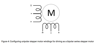
    Make sure you used the correct 4 of 6 wires per this diagram in Drive unipolar stepper motors as bipolar stepper motors with a simple wiring reconfiguration

    Let me look into that motor and see if we have similar, and I'll ask some coworkers for help. 

    Regards,

    Jacob

  • Hello Jacob,

    I have tried with the different TOFF but the noise is still there. 

    Yes, I have verified the motor connection. It is same as your recommendation.

    Did you get the chance to check with your co-workers for the motor?

    Regards,

    Guru Hegde

  • Hello Jacob,

    I also wanted to know the calculation of the voltage dividers for the VREF pin while using PWM to control the current. Can you please share the details for the same?

    Thanks,

    Guru Hegde

  • Hey Guru, 

    I talked with a coworker, and his feedback was that the TOFF pin doubles as TOFF in STDD and % ripple in STRC.  To achieve the lowest possible ripple (which I think he is complaining about), you can set the TOFF pin = 0 (GND).  

    I also wanted to know the calculation of the voltage dividers for the VREF pin while using PWM to control the current. Can you please share the details for the same?

    You can use an online PWM DAC calculator to help simulate this.  See Method for Converting a PWM Output to an Analog Output   or Low-Pass Filter a PWM Signal into an Analog Voltage for a better explanation, our datasheet image suggests a 2nd order filter.

    Regards,

    Jacob

  • Hello Jacob,

    With Toff set to GND(0V) we are able to reduce the noise. But if the step frequency is less the motor makes some noise. If it increases the noise will vanishes. Could you please let me know what might be the reason?

    Also want to know is there any calculation for minimum hold current for the stepper motor?

    Please suggest.

    Thanks and Regards,

    Guru Hegde

  • Hey Guru, 

    The noise changing with speed is a normal behavior of any stepper motor.  You can see our note How to Reduce Audible Noise in Stepper Motors for a lot of good info about it.  Without changing your microstepping setting to something finer you might not be able to improve it much. 

    Minimum hold current will depend on your application as well, depending on the load on the motor shaft.  You could follow the calculations in 8.2.4.1 Power Dissipation and calculate your holding current to target a 15°C rise in driver temperature or similar if you wanted to, but I would just choose your holding current through bench testing in your system.  

    Regards,

    Jacob

  • Hello Jacob,

    Hope you are doing well.

    If we kept VREF as high (3.3V) we are not getting any noise from the motor. But we want to make sure that the motor is moving as per our requirements when VREF is high. Could you please let us know the encoder which measure the movement of the motor?

    Thanks 

    Guru Hegde

  • Hey Guru,

    I'm not sure what you mean.  You can use any encoder you want.  For a personal project I've used the AMT102-V from CUI Devices for monitoring a stepper motor.  

    Regards,

    Jacob