Hi Team,
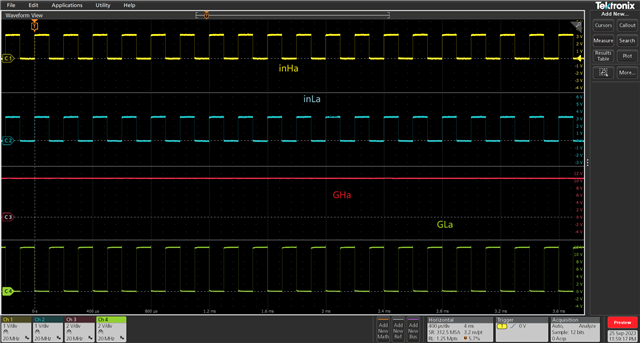
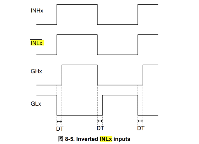
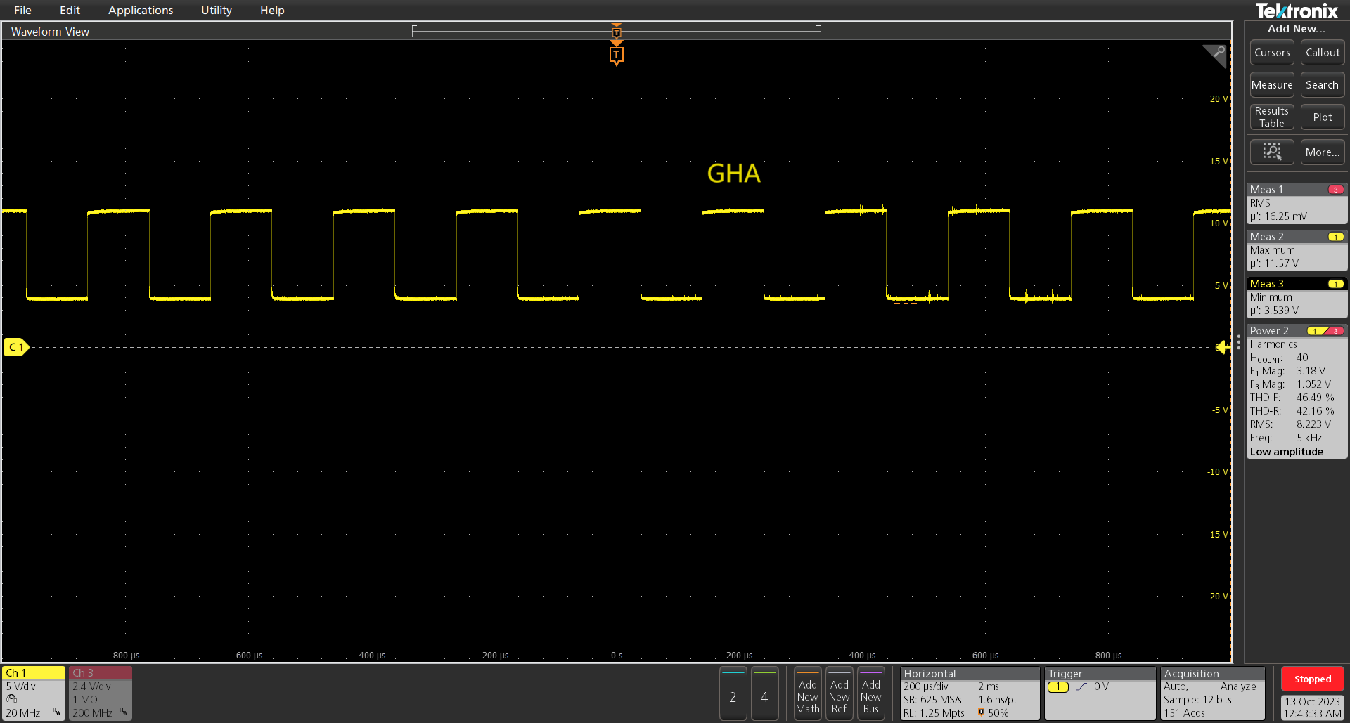
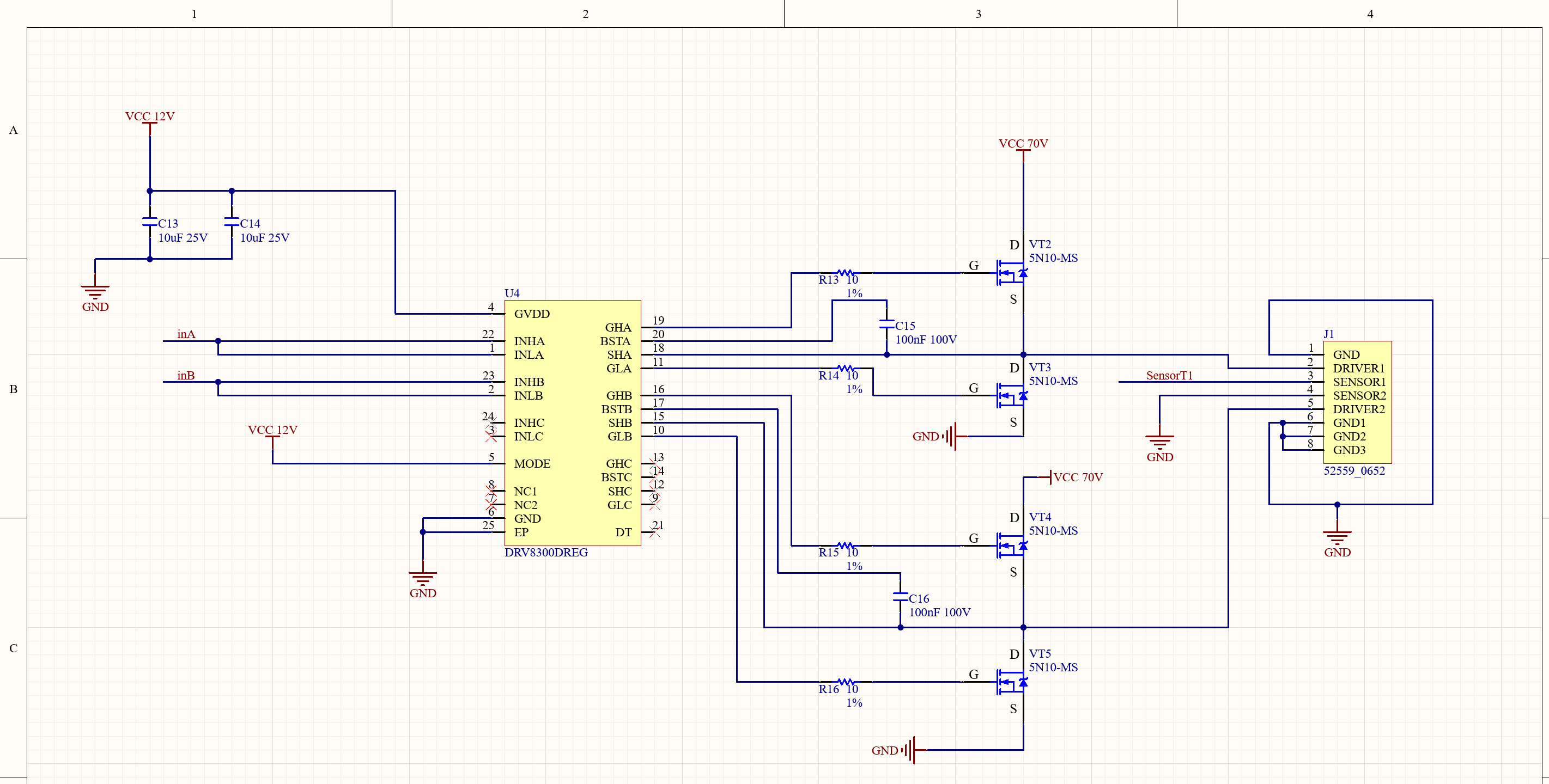
In inLx flip mode, give inHx and inLx the same non-100% duty cycle PWM waveform. GHx output is always high and GLX can output flip voltage properly. Could you help check this case? Thanks.
Best Regards,
Cherry
Hi Team,
In inLx flip mode, give inHx and inLx the same non-100% duty cycle PWM waveform. GHx output is always high and GLX can output flip voltage properly. Could you help check this case? Thanks.
Best Regards,
Cherry