


What are the recommended limits for the capacitance of C_VCP at 0V and 10V (where it operates)? The TRM just says "1 uF 16V". I chose a capacitor meeting those recommendations, but it wasn't big enough, so I'm looking for more guidance on choosing a better one without overstressing the charge pump or causing startup problems. Also it looks like the EVM uses a 1 uF 100V capacitor, which is much larger, I'm hoping to stay with an 0603 capacitor.
I have a design using the DRV8353S driving 12x IPTG014N10NM5ATMA1 (2 in parallel on each leg). My latest version was struggling with VCP undervoltage faults when I used a CL10B105KA8NNN (1 uF 0603 25V, 0.55 uF at 10.5V). Looking at with a scope, the VCP regulator was clearly failing to maintain its output switching at 20 kHz (I forgot to even save a picture, it was never going to work). Adding a second of those capacitors seems to have addressed the problem, but that seems to be more capacitance than is recommended.
For future revisions, I found GRM188R61H225KE11. It has a 2.2 uF nominal capacitance, but it's still under 1 uF at 10V of DC bias. Would using that pose any problems?
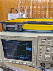
Here's what VCP looks like with two CL10B105KA8NNN in parallel (at ~0% duty cycle, so all 3 half bridges are switching at almost the same time, which should be the worst case):
I'm switching at 10 kHz - 20 kHz (subject to optimization, no particular requirements) with FOC (SVM, so it's switching each gate every cycle). Gate charge for each FET is 169 nC typical. This is close to the 25 mA limit on the gate drive power supplies, but it should be within it. My design is for 65V nominal motor voltage, with a 15V supply provided to VM.
