Hello,
Unfortunately 1 of our evaluation boards has damage, and I would like to make sure why exactly this happened. Our test setup was as following:
Board/Schematic: MD047A / Assembly 003
disconnected J4 PH/IN2_MCU and J4 EN/IN1_MCU
VM=30.7V (with a power supply delta ES030-5 at Batt and Gnd)
IPROPI =2.2k
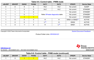
PWM mode
Coil: 12mH / 1.1Ohm (connected to OUT1 and OUT2)
connected PWM signals to IN1/IN2 as in image below:

PWM: 20kHz, dutycycle about 50%, amplitude 3V
CH1 = IN1
CH2 = IN2
CH3 = OUT1
CH4 = OUT2
In the image, SR = 4V/us.
I set the SR to 43V/us via the GUI (0.5.0), current on VM goes in CC (5A), and the board (probably DRV8244) has been damaged.
Could the overlap in IN1 and IN2 (both high for approx. 800ns) in combination with the high SR be the problem?
Kind regards,
Rob