Hi team,
As I know that we can calculate the full-scale of output current as below equation as use TRQ_DAC to adjust scale.

But how can I know the real output current value when the device work?
BR,
Jimmy
This thread has been locked.
If you have a related question, please click the "Ask a related question" button in the top right corner. The newly created question will be automatically linked to this question.
Hi team,
As I know that we can calculate the full-scale of output current as below equation as use TRQ_DAC to adjust scale.

But how can I know the real output current value when the device work?
BR,
Jimmy
Hi Jimmy,
You will have to use an oscilloscope current probe for looking at the current waveform and IFS peak current using an oscilloscope. This is the most commonly used method in stepper drivers. Alternatively you can connect a true RMS meter in series with the A or B phases and calculate the IFS peak based on the RMS voltage.
Regards, Murugavel
Hi Murugavel,
I use step motor(1 phase, 25degree, 64+-7% output shaft, gear reduction ratio 1/64, 20 ohms resistance per phase) for loading, Vref = 3.3V, TRQ_DAC = 100% and Vin=9V.
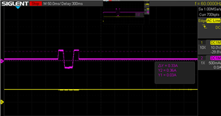
As I know Vref=3.3 and TRQ_DAC = 100%, Does the IFS = 1.5A mean Iout scale peak to peak = 1.5A to -1.5A? how about output current? Is 9V / 20ohms = 450mA Ipeak? But my test result the output current Ipeak is 330mA. Could you tell me where I'm going wrong?

BR,
Jimmy
Hi Jimmy,
You said "As I know Vref=3.3 and TRQ_DAC = 100%, Does the IFS = 1.5A mean Iout scale peak to peak = 1.5A to -1.5A? ". Yes this is correct. However for current regulation to work at the desired IFS, IFS x Rcoil must be sufficiently greater than (VM + V-BEMF). When the motor is not spinning V-BEMF = 0. When the motor is spinning V-BEMF is a finite value that opposes the VM voltage and reduce available voltage across the coil by that amount, which will impact the maximum IFS that can be achieved while the motor is spinning. It is also important VM voltage does not reduce when loaded (good voltage regulation). If it does it will also impact the maximum current reached.
"how about output current? Is 9V / 20ohms = 450mA Ipeak?" Yes in the case where VM = 9V even if VREF is set for IFS = 1.5 A drive current cannot exceed 450 mA IFS with a 20 Ω DCR motor load. What is the microstep mode you are using and what is the step input PPS used? I assume the pink trace is the current waveform. It does not look like what I'd expect. Is it full-step mode? So, only two step pulses were issued? How did the current return to zero after moving steps?
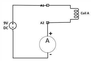
Did you measure the DCR of the coil with a multimeter? Often times they don't exactly match the datasheet of the motor. You can do this simple experiment and measure the maximum DC current (with a multimeter) through the coil with 9V DC across the coil - see image below. Then you can connect the coil to the driver, enable the driver and see what the current reading using the same meter is, at standstill with VREF = 3.3V and TRQ_DAC = 100%, immediately after wakeup nSLEEP = 1, and no STEP pulses issued.

Regards, Murugavel