This thread has been locked.

If you have a related question, please click the "Ask a related question" button in the top right corner. The newly created question will be automatically linked to this question.

BOOSTXL-DRV8323RH: Temperature and fault light issue

Part Number: BOOSTXL-DRV8323RH
Other Parts Discussed in Thread: DRV8323

Hi Team,

The DRV8323RH development board is being used.

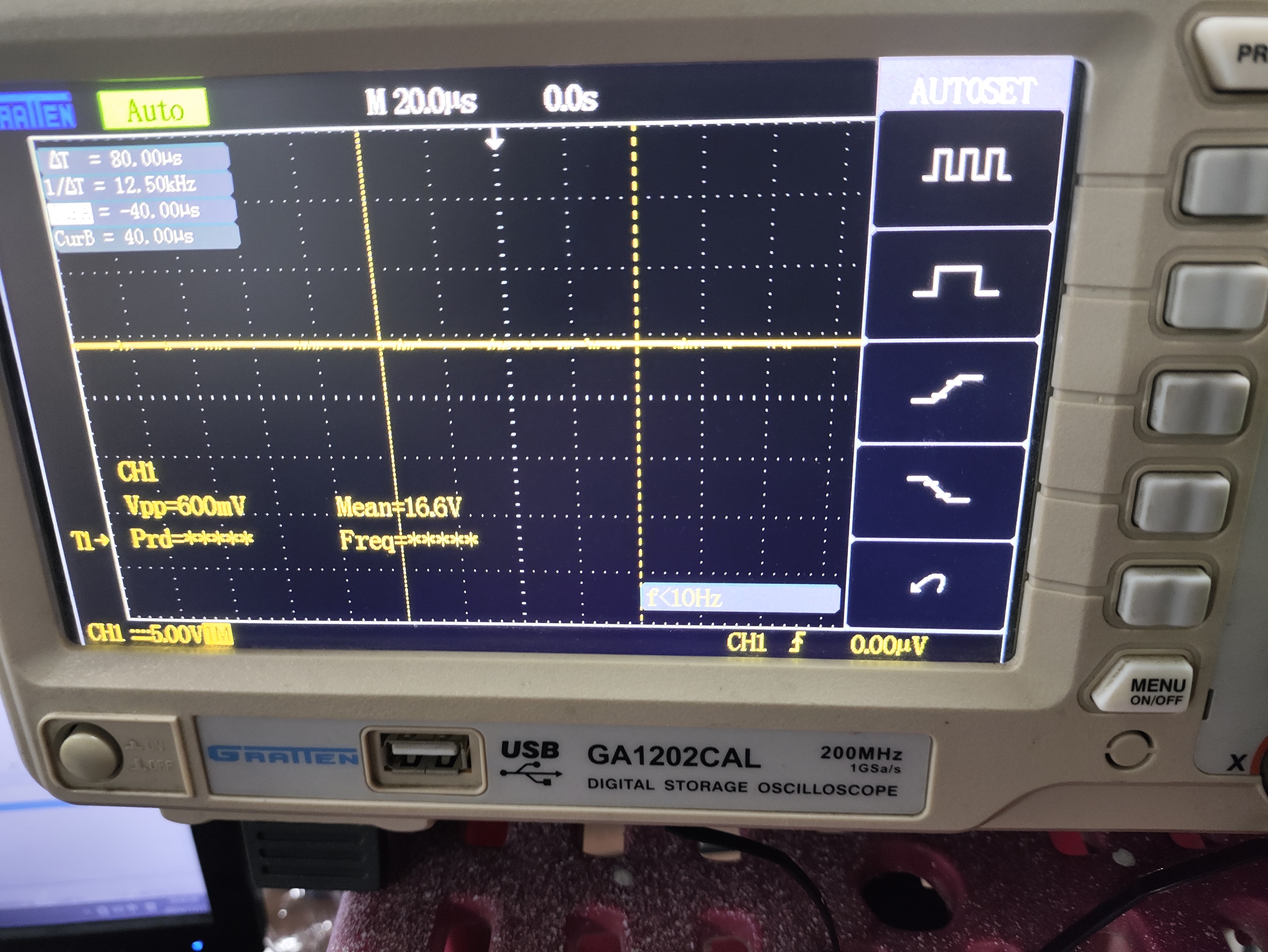
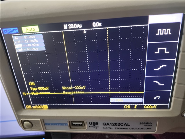
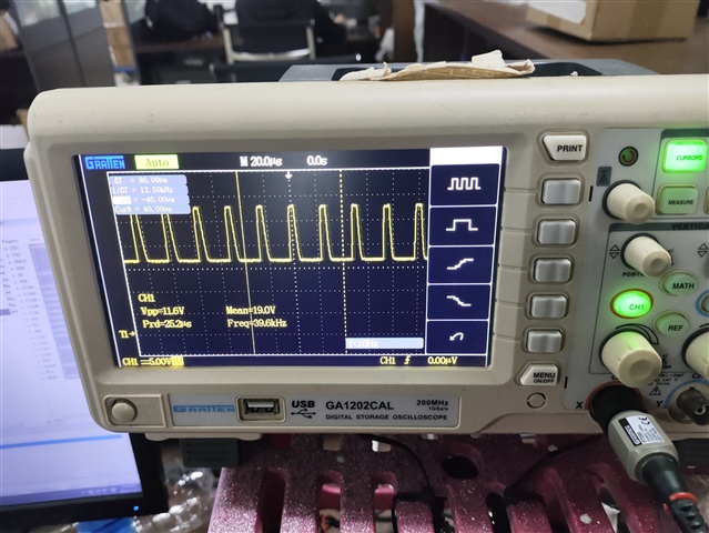
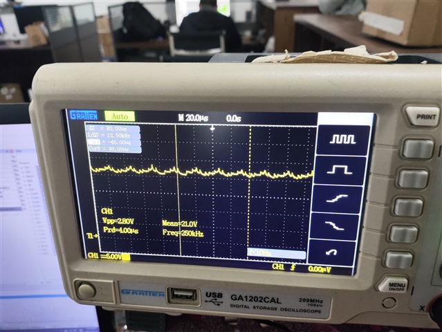
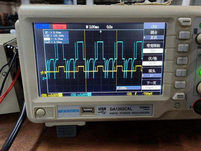
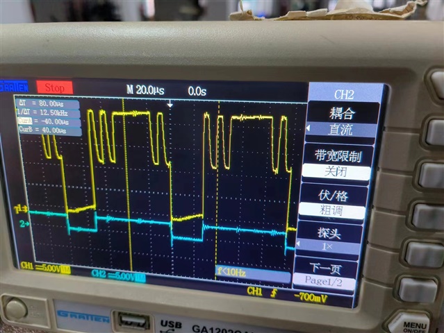
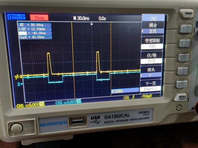
The 8323 chip was replaced two times, one of the chips was hot after power up and no short circuit condition was found while the other chip powers up normally. When a high signal is sent to the INHX pin of the 8323, it does not function properly and the fault light is on.

Could you help check this case? Thanks.

Best Regards,

Cherry

  • Hi Cherry,  

    Can you provide the test conditions/parameters used for both these instances?  And were you able to operate the device normally at any point,  or only experience these two issues with the replacements? 

    Best Regards, 

    -Joshua

  • Hi Joshua,

    Thank you for the support.

    Can you provide the test conditions/parameters used for both these instances? 

    Power the development board 16V using 3xPWM mode. INLx is always a high signal and INHx is a PWM signa. INHx will report an error as soon as it is pulled high. The other chip will get hot once it is powered by 16V.

    And were you able to operate the device normally at any point,  or only experience these two issues with the replacements? 

    This issue is only encountered with the replacements, but there are 3 chips have this issue where once the signal is pulled high, the error is reported.

    Thanks and regards,

    Cherry

  • Hi Cherry,  

    When INLx is HIGH and INHx is pulled high,  can you check GH/GL/SH/SLx  voltage waveforms to determine if there is any shoot through occuring? If the high and low side of a phase is forced HIGH,  it is possible the heating and fault might be due to an overrcurent fault .

    You said there was no short circuit condition,  but can we confirm device operation with those waveforms showing the deadtime? 

    Best Regards, 

    -Joshua

  • Hi Joshua,

    The figures of the 3 GH signals when a non-working chip begins to power on and not give a signal are as follows: 

    GL signals are as follows:

    The voltage supplied is 16V, and the chip gets hot as soon as it is applied, but it does not report any error. When the PWM signal is given, the GH GL signal is still as shown in the figure above, but a fault is reported, regardless of which low input is pulled high.

    Error only occurs when power is applied and signal is not applied, the voltage value for GHC is 21 V, the voltage value for GLC is 200 mV, and the voltage values for a and B are 16 V.

    When the low inputs of a and B are pulled high and no error is reported, the GH outputs are as follows:

    However, when the C low input is pulled high, the output signal of the GHC is as follows: 

    Thanks and regards,

    Cherry

  • Thanks for this information, Cherry,  

    Let me talk with my team about this issue and follow up this week.  I'll keep you updated on any suggestions.

    Best Regards, 

    -Joshua 

  • Hi Joshua,

    Just give some updates for more tests:

    In 3xPWM mode, the PWM frequency is 20 kHz and the error in sending the PWM wave still occurs. The following are the fault and enable signals:

    The INH signal and fault signals are as follows:

    The waveforms and fault signals for the GHC are as follows:

    They have also tested the 1KHzPWM waveform. The following figure shows the fault signal and GHB output waveforms:

    The following figure shows the 100-Hz fault signal and GHB output waveform:

    The following figure shows the GHB signal and INHB input signal waveforms at 5 KHz:

    The following figure shows the GLB signal and INLB input signal waveforms at 5 KHz:

    The current resistance between GHX and SHX is 470 kΩ and GLX to ground is 149 kΩ.

    Thanks and regards,

    Cherry

  • Hi Cherry,

    Thanks for the additional info - our team is currently OOO on US Holiday break, but will return next week. 

    Please anticipate a delayed reply, and feel free to share further details that may help the debug in the meantime.

    Best Regards, 
    Andrew 

  • Hi Andrew,

    Thank you for the notice and just adding one more concern, 

    Can the VDRAIN pin be connected directly to VM instead of the MOS tube? Since this is the design of the customer board currently and they are wondering if there be any effect if this connection is made? 

    Thanks and regards,

    Cherry

  • Hi Cherry,  

    Thank you for the added info! 

    Regarding your last question,  I believe there should be no major issue connecting VDRAIN to VM as long as they are being supplied with a single voltage supply, and the bulk capacitance is sufficient for VM and the power stage. 

    And I am still looking into this behavior and will follow up within the week after overview of your new tests. 

    Thank you for your patience and Best Regards, 

    -Joshua 

  • Hi Joshua,

    Thank you and expect your response.

    Thanks and regards,

    Cherry

  • Of course,  Cherry. 

    Thank you for your patience as I aim to update you before the end of the week. 

    Best Regards, 

    -Joshua 

  • Hello Joshua,

    May I know is there any updates at your end?

    Thanks and regards,

    Cherry

  • Hi Cherry,  I apologize for delay in communications , I am still looking into this matter and will update you on Tuesday. 

    Best Regards, 

    -Joshua

  • Hi Cherry,

    Many of our team members are currently out of office for US holiday timeframe - but will be back in office by 1st week of January.

    Please anticipate a delayed response & feel free to provide additional information in the meantime.
    Best Regards,
    Andrew

  • Hi Cherry,  

    Apologies for the very long delay due to the holidays! 

    We look forward to continue providing support to close this issue,  and will aim to follow-up this week. 

    Best Regards, 

    -Joshua

  • Hi Cherry, 

    I apologize for the long delay in support for this issue.

    If there is still interest in resolving the matter, I have the comments below: 

    If this occurs only on the specific IC and the EVM works normally when replaced with another DRV8323, it appears the device was most likely internally damaged due to a violation of abs max. It was said that there is no shorting condition observed, but can you provide the resistance measurements of all Gates (GHx/GLx), VM, VDRAIN, and VCP on the working device, as well as on the unit experiencing issues?  

    Has this issue occurred on any other evaluation boards used, or is this a single instance?

    And lastly, can we also confirm if the IC/board behaved correctly at an point in time before the heating issue started?

    Thank You and Best Regards,

    -Joshua