This thread has been locked.

If you have a related question, please click the "Ask a related question" button in the top right corner. The newly created question will be automatically linked to this question.

DRV8343-Q1: DRV8343S generator mode

Part Number: DRV8343-Q1

Good day, colleagues,

Customer has a question regarding DRV8343S:

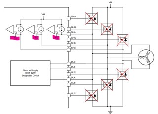
We are using the gate driver for a BLDC fuel pump application in the following configuration:

Datasheet p.78:

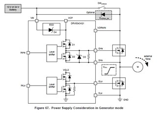
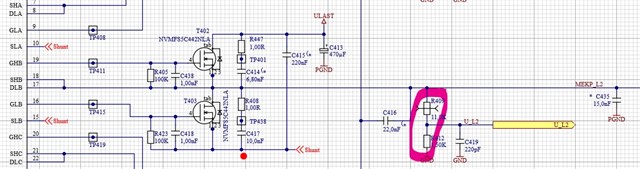
The VDrain switch in our case is double FET (B2B) which is controlled by VCP to disconnect the driver stage and other consumer.

VM has a simple diode as reverse polarity protection and is permanently powered.

The pump does not run in generator mode so we did not implement the VDrain/VM  diode.

 Now we discovered in the maximum ratings that the difference of VM and VDrain must not be above +-10V


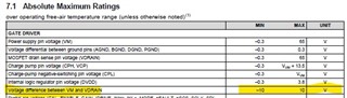
In the above configuration we will have VM – Vdrain > 10V if the switch is disabled.


Can you confirm that we can use the DRV8343 with the switch between VM and VDrain regardless what the maximum ratings say here?

Thank you,

Daria

  • Hi Daria,  

    Thank you for your question. 

    Allow me some time this week to look into this specific configuration and then update you with any major possible drawbacks or suggestions. 

    Best Regards, 

    -Joshua 

  • Hi Joshua,

    Any updates? Let me know if you need more data.

    Thanks,

    Daria

  • Hi Daria,  

    Sorry for the delay,  but let me confirm some information regarding this configuration with my team and follow up by Wednesday. 

    Best Regards, 

    -Joshua 

  • Hi Daria,  

    I can't recommend to ignore the AbsMax specifications on our device here,  as having that large differential can lead to abnormal device operation or internal damage. 

    How much do you calculate the potential differential voltage to be, and is there the possibility to keep the value within range with this configuration and application?  If not,  then I cannot recommend violating that condition. 

    Best Regards, 

    -Joshua

  • Hi Joshua,

    They are in a 12V system. This alone will violate the 10V not to talk about the operating range and so on.

    In the meantime they face another issue with the offline diagnostics:

    When we run the build in shorts test we get a short to GND. This is most likely caused by our phase voltage measurement with a 12,5kOhm voltage divider to GND. If we increase the resistance value to around 50kOhm the problem disappears.


    Is there any possibility to adjust the Vth thresholds for the short to GND test?

    What are the recommendations for phase voltage measurements? The data sheet does not give any hints.

    Thanks,

    Daria

  • Hi Daria,  

    Thank you for the clarification on the voltage. 

    Regarding the second question,  I may not be understanding correctly about this test.  Can you please clarify what you mean by recommendations for phase voltage measurements? 

    Best Regards, 

    -Joshua

  • Hi Joshua,

    For the gate driver we use this circuitry as power stage, including the voltage divider (pink) to measure the phase voltages.

    It needs to be somehow low ohmic to be fast enough

    When we start the short test in this configuration we get a short to GND flagged. A try with a resistor to ULAST on the other hand shows a short to ULAST.

    When we remove the voltage divider or increase it to over 50kOhm the gate driver behaves as described in the specification.

    Since we have not found any recommendation in the spec for a phase voltage measurement the below question came up.

    Regarding the VM/VDRAIN topic I would remove the following application example with the SW_Vdrain on p.78,

    as it is violates the maximum ratings of the specification and misleads the user.

    Thanks,

    Daria

  • Hi Daria, 

    Thank you for the explanation on the matter, and this week I will be looking into this with my team to get better feedback on your question and datasheet observations. 

    Best Regards,

    -Joshua

  • Hi Daria, 

    Many of our team members are currently out of office for US holiday timeframe - but will be back in office by 1st week of January.

    Please anticipate a delayed response & feel free to provide additional information in the meantime.
    Best Regards,
    Andrew

  • Hi Daria, 

    This behavior of the voltage divider appears correct, as a low enough resistance path on the phase outputs will be characterized as a short and external voltage sensing of that method may not be desirable.  

    Is using the appropriate current shunt resistors to measure motor feedback not feasible in this application? If the concern is only protection, the DRV8343S-Q1 also utilizes VDS voltage monitors to protect against overcurrent as well as an internal Zener diode to protect against overvoltage on the external FETs.

    And thank you for the datasheet observations and feedback. 

    Best Regards,

    -Joshua