This thread has been locked.

If you have a related question, please click the "Ask a related question" button in the top right corner. The newly created question will be automatically linked to this question.

TPIC2060A: FG signal speed measurement issue

Part Number: TPIC2060A

Hi Team,

The spindle coil data (0x8324) can now be controlled by using 10M SPI data rate in the DSP STM C6678 (1G) IC single core master and the spindle motor can function.

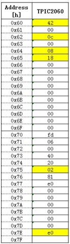
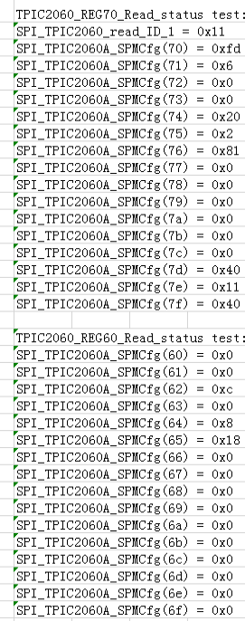
According to the IC specification, BIT0 bit FG signal.Spindle rotaion *** for speed monitor in REG7F. With 0x8324 data control, the FG signal is at an oscilloscope frequency of 2.9684 kHz (336us) and the REG7F read by the DSP main program is continuously changing.

1) Can the speed of the spindle be controlled by reading the frequency of FG change of REG7F?

2) The DSP chip operates at 1 GHz, which theoretically runs at 1 ns, plus an 8-bit transfer read of SPI (10M). ・・・ (8+2)・100ns=1us. Theoretically read 336/(1*2) = 168 high or 168 low. FG(BIT0) of REG7 read in emulated state is continuously tripping. Could you help check are these calculations correct? 

Could you help check this case? Thanks.

Best Regards,

Cherry

  • 1) Yes, spindle speed (FG) can be monitored at bit0, REG7F.  

    2) Serial communication requires 16 clocks, 1.6us for one communication.  

    Can you monitor XFG (signal at pin12) by oscilloscope? By monitoring XFG, you can confirm actual FG signal and compare with Bit0/REG7Fh.

    Best regards,

    Norikazu

  • Hi Norikazu,

    Thank you for the support.

    2) Serial communication requires 16 clocks, 1.6us for one communication.  

    Can you monitor XFG (signal at pin12) by oscilloscope? By monitoring XFG, you can confirm actual FG signal and compare with Bit0/REG7Fh.

    With 10M frequency control, one communication time is 1.6us. If REG fill is taken consecutively, this is equal to the sampling period of 1.6us. At the same time, the period for looking at FG on the oscilloscope is 694us and the half-period is 347us, and the period shown on the oscilloscope is also stable. Reading the FG status is continuous high or low according to 347/1.6 = 216 times.

    However, in the emulator state, viewing the log information read register FG status in the PC window changes quickly without continuous high or low signal status. The DSP also reads the FG output signal via GPIO, and the behavior is also similar.

    SPI_TPIC2060A_FGRegStatus = 0x0

    SPI_TPIC2060A_FGRegStatus = 0x1

    SPI_TPIC2060A_FGRegStatus = 0x0

    SPI_TPIC2060A_FGRegStatus = 0x1

    SPI_TPIC2060A_FGRegStatus = 0x1

    SPI_TPIC2060A_FGRegStatus = 0x1

    SPI_TPIC2060A_FGRegStatus = 0x1

    SPI_TPIC2060A_FGRegStatus = 0x1

    SPI_TPIC2060A_FGRegStatus = 0x0

    SPI_TPIC2060A_FGRegStatus = 0x1

    SPI_TPIC2060A_FGRegStatus = 0x0

    SPI_TPIC2060A_FGRegStatus = 0x0

    SPI_TPIC2060A_FGRegStatus = 0x0

    SPI_TPIC2060A_FGRegStatus = 0x0

    SPI_TPIC2060A_FGRegStatus = 0x1

    Thanks and regards,

    Cherry

  • Would you try the setting below if the bit is 0?

    REG64, Bit3 = 1.

    Best regards,

    Norikazu

  • Hi Norikazu,

    The figure above shows the values written to the relevant registers at initialization where REG64 writes 0x08, which is BIT3 set to 1.

    When set, all registers are read as follows:

    Where reg74 sometimes reads 41 (0100 0001) and sometimes 01. Monitor event flag Bit6 pointing to REG7D(0X40) is XRSTIN_DET(XRSTIN event flag 1=detect low event in XRSTIN pin) this pin is pulled high (held in communication) by the DSP GPIO during test, followed by reading and writing of the associated registers.

    For real-time acquisition,

    1)  for example, on a single core system, if the FG signal is collected in a loop in the main program, the run time of each program needs to be considered. If the time for each loop execution is calculated, is it the time for each sample?

    2) If the acquired program is placed in an interrupt, is the sample period equal to the interrupt time plus the time to read FG?

    3) Do you count the FG pulses during the sampling period to determine the speed calculation of the spindle?

    Thanks and regards,

    Cherry

  • REG74 Bit 6 is reserved bit and nothing is assigned. This bit should not be changed. REG7D bit6 is set when XRSTIN is pulled down. (Reset input). If the bit is 1, it means DSP resets TPIC2060A.

    I don't have answer to your questions about DSP program and interrupt routine because I don't have information about DSP.  For question 3), TPIC2060AS does not count the FG pulses to calculate the speed, TPIC2060AS detects filtered FG signal to determine the timing for driving next phase. DSP need to calculate the speed and change the VSPM DAC value to adjust the speed. 

    It looks register value is not read correctly or unintentional XRSTIN happens.

    Is spindle motor rotating as expected?  What about other motor drivers?  Works fine? 

    Best regards,

    Norikazu 

  • Hi Norikazu,

    REG74 Bit 6 is reserved bit and nothing is assigned.

    The register status write of REG74 to 0x20, which starts the status of the STAUS_on_VFCS function. The power-up register read is also 0x20. 

    Customer has corrected it.

    . DSP need to calculate the speed and change the VSPM DAC value to adjust the speed. 

    If the DAC value is larger, the spindle speed is faster, and the signal period of FG is shorter, right? However, when the DAC value is written to 0x324, the measured FG period under the oscilloscope is 694us and the signal period is stable and long. Reading the FG register is changed very quickly for a fixed sample period and has no pattern.

    It looks register value is not read correctly or unintentional XRSTIN happens.

    Register 7E Version is always 0x11 and the data written to it can be read correctly.

    Unintentional XRSTIN: Register 7D is 0x00 state, the possibility of this case is small.

    With the same program, a read of REG0X7D is 0x40, reloading the program and then running it, it will read as 0x00.

    Is spindle motor rotating as expected?  What about other motor drivers?  Works fine? 

    Now that the spindle speed is proportional to the VSPM DAC data size, the SLEDGE motor can run properly in full step. 

    For question 3), TPIC2060AS does not count the FG pulses to calculate the speed, TPIC2060AS detects filtered FG signal to determine the timing for driving next phase. DSP need to calculate the speed and change the VSPM DAC value to adjust the speed. 

    Does the FG pin output level of the TPIC2060 chip match the data read from the FG register?

    1) The spindle timing control of the TPIC2060AS is that the VSPM DAC value is not changed internally to adjust the speed based on the FG signal, but the DSP is required to read the FG data for data update, correct?

    2) The FG signal observed on an oscilloscope is a periodic square wave signal. According to the customer understanding, the larger the VSPM DAC's data, the smaller the FG change period, and the faster the spindle speed.

    The implementation in their design is assumed as follows: 

    The spindle speed is calculated (fast speed adjustment, phase adjustment after speed range) by counting the high and low levels of the FG signal in the program to calculate the rise time and fall time and duty cycle.

    Issue: With the program high-speed sampling rate at the same VSPM DAC value, the duty cycle variation of the acquisition FG level does not match the oscilloscope display. Is the period method to scale FG by reading the FG signal for cycle count correct?

    Could you help look into it? Thanks.

    Best Regards,

    Cherry

  • Hi,

    May I know is there any updates?

    Thanks and regards,

    Cherry

  • Even though VSPM DAC is no change, spindle motor speed would change (temperature, supply voltage and others would be changed), DSP needs to monitor FG signal to adjust the speed at the target speed.

    Regarding FG bit, can you try REG75 bit 0 (SPM_HIZMODE=1) and read FG bit after spindle motor reaches to the target speed?

    Spindle driver noise can be eliminated if output is in HiZ.

    Best regards,

    Norikazu