Other Parts Discussed in Thread: DRV8889-Q1
it is an inquiry regarding the output current when driving a stepping motor.
I would like to inquire about the current waveform that occurs when driving at low and high speeds under the stepping motor driving conditions of the DRV8889-Q1EVM.
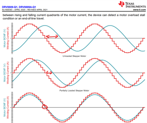
Drive input voltage : 12[V] , current limit of stepping motor : 500[mA] When driven, the coil outputs a waveform as shown below. This is a comparison of the waveform of the applied current according to speed.
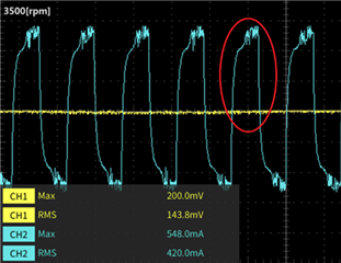
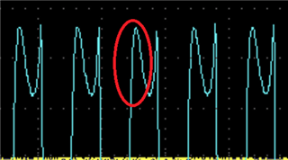
1.3500rpm
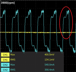
2.3900rpm
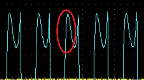
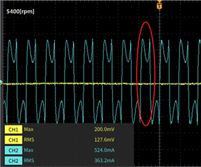
3.5400rpm
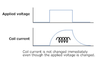
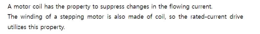
I understand current waveform of 3500~3900[rpm]. This is because as the speed increases, the waveform of the current applied to the coil changes due to the inductance of the windings.
![]()
* www.pulsemotor.com/.../stepping-motor-drive-IC_04.html
However, at 5400[rpm], the current waveform shows different characteristics from 3500~3900[rpm]. The front part of the applied electric current should be attenuated, rather it shows a size close to the limiting current.
As the speed increases, the inductance and back electromotive voltage increase, so the size of the current applied to the stepping motor should decrease, rather it shows the opposite tendency.
Could you please explain the reason for this phenomenon?
- Does the drive apply boost voltage?
- Explains how to disable and test the boosting feature
- Request for operating conditions and principles of the boosting feature
- Comparison of windings input value differences depending on the boosting feature operation.