This thread has been locked.

If you have a related question, please click the "Ask a related question" button in the top right corner. The newly created question will be automatically linked to this question.

INA253EVM: Current Sensor Placement in Single Phase Half-Bridge Inverters Closed Current Loop PI Controlled

Part Number: INA253EVM
Other Parts Discussed in Thread: INA253

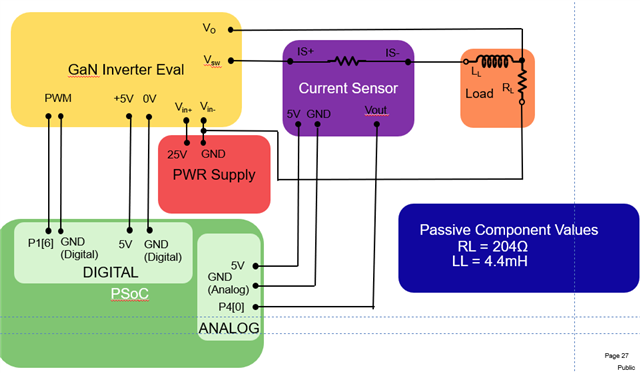
My name is Jonah Yu, I am a researcher working on developing the electronics and software development for one of our motor control FuMos and ran into a problem with our current sensor feedback. I am using a PSoC 5LP development kit from Cypress as the controller for the closed loop. For the inverter I am using a half-bridge with gate driver on an evaluation board. For the current-shunt sensor I am using TI's  INA253EVM evaluation board. It seems when I place the sensor in series between the midpoint of the half bridge (Vsw) and the load, the current values are incorrect. They are than the power supply's current limit (500mA). However, when the sensor is placed in series between the power supply positive terminal and the high point of the half bridge (Vin+), the value agrees with the current value on the power supply. Is there a conventional place to put the INA253EVM for high side sensing in a closed current PI controlled loop? I have seen the manual place the sensor between the half-bridge midpoint and the load, but the current values do not seem to match with hand calculations and the current from the power supply for the drive inverter. The PWM frequency is about 122kHz with a period of 8.146us.

  • Hello Jonah,

    I believe this is an issue with the PWM and the bandwidth of the device. The second location you are not having the issues because the PWM voltage is not switching.  Even with the enhancement of the PWM rejection I believe you are still having issue with the recovery.  With the period being 8.146µs and for example if you have 20% PWM duty cycle the makes the time between PWM switching 1.6µs.  If you look at figure 25 in the datasheet you will see that the output just starts to settle about about 1µs.  So you may be getting some of the unsettled signal introduced.  We do have a device that is better but you would still have issue with the PWM.  The INA241 has a limit of 125kHz but it states in the datasheet that the transition from PWM states must be longer than 3µS.  Also this device does not have an integrated shunt.  The other solution is the INA296 that is as fast as the INA241 but does not have PWM rejection the reason I suggest this is that it does not hold the output for 1µs but recovers fast enough that it may not be an issue for you.    

    To prove this out try to reduce your PWM timing and determine if the INA253 will still work for you.

    Regards,

    Javier

  • Hello Jonah,

    Could you give a scope shot to prove this out?  Can you sense the VCM seen at the INA253 and the PWM switching along with the Vout of the INA253?