This thread has been locked.

If you have a related question, please click the "Ask a related question" button in the top right corner. The newly created question will be automatically linked to this question.

DRV2700:  DRV2700:The DRV2700 boost board is not functioning

Part Number: DRV2700

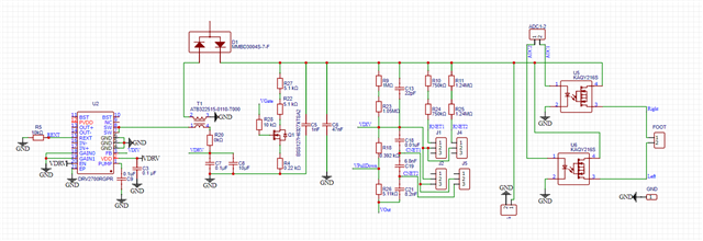
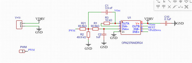
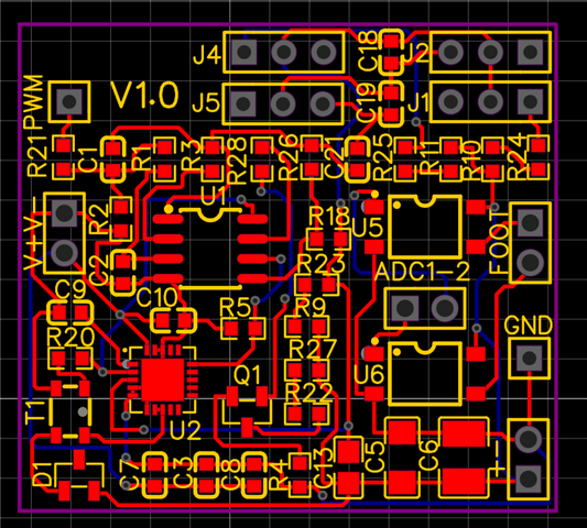
Hello, I'm using the DRV2700 chip and designed a boost power supply PCB to elevate the voltage to 500V based on the boost circuit in the chip manual. After soldering, I found that without inputting a signal, the output voltage is only a few volts. However, it is increasing very, very slowly, and it is far from reaching the desired 500V. Could you please tell me if there is an issue with my circuit?

  • Hello,

    I am not noticing anything wrong with you circuit, it is very similar to our EVM. Can you provide the position of jumpers J1, J2, J4, and J5 that you are testing with?

    Regards,
    Sydney Northcutt 

  • Thank you for your help! As you can see, my J1, J2, J4, J5 are used to replace SW1 and SW2 in the EVM. In my test, I didn't use jumpers to connect them, and I know that's not right, but it shouldn't have no output at all. Do you know what to pay attention to when soldering the chip? I suspect that the chip is broken.

  • Hello,

    Are you not getting an output at all or are you getting a few volts? What value are you using for VDRV? I recommend placing jumpers on the equivalents of SW1 and SW2 to replicate one of the scenarios of the EVM. Having your jumpers open alters the feedback voltage fed back to the device, which can alter operation. From here we can better determine the chip is damaged. For soldering, I would double check the connection of all the pins and ensure no pins were bridged. 

    Regards,
    Sydney Northcutt