This thread has been locked.

If you have a related question, please click the "Ask a related question" button in the top right corner. The newly created question will be automatically linked to this question.

MCF8315A: Continuing problems with controlling this chip

Part Number: MCF8315A

My struggle with MCF8315A continues!

Finally, I am (sort of) able to control it from my own software, but it never behaves as expected. 

First I load a default set of registers which I set up after spending many hours with the Motor Studio and the EVM.

Then before I do anything with it, I initiate MPET and wait unti I get value 0 in register 0x190.

Then I try to run the motor at different speeds, and the result is far from my expectations. That, assuming MPET had finished (because sometimes it goes on forever until a power cycle).

The motor kicks, sometimes moves in the opposite direction or in the same direction but at different speed, then changes to some other speed, but not what I wanted. Sometimes it just vibrates with no rotation at all. Sometimes it fails to stop. It is just unpredictable.

My motor is 42BL41.010.

All I want is to give the motor a certain speed to spin at. How hard can that be with MCF8315A with all those registers in it?

Thanks!

  • Hi Konstantin,

    1. Could you provide a capture of the phase current during startup, open loop, and closed loop? I assume that the motor changing speed is due to the motor transitioning from open loop to closed loop but I want to make sure that this is the issue that is occurring.

    2. When does the motor "kick" during startup? If so, can you try and lower the value for ALIGN_OR_SLOW_CURRENT_ILIMIT, bits 20-17 in register MOTOR_STARTUP1 (84h). If the align current threshold is too high the motor may not be settling in time which can lead to the motor vibrating without spinning and kicking. You can also try and increase the value for ALIGN_TIME, bits 24-21 in register MOTOR_STARTUP1 (84h).

    3. Can you provide the value you input into MAX_SPEED, bits 13-0 in register CLOSED_LOOP4 (8Eh)?

    Regards,

    Joshua

  • Hi Joshua,

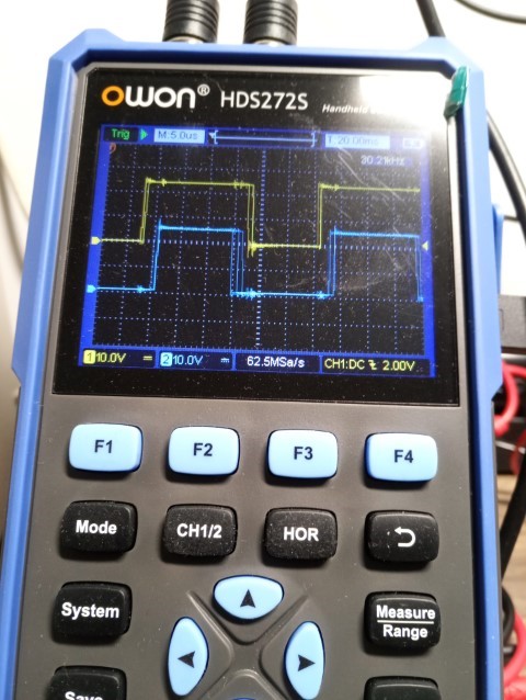
    This is what my phases look like (unfortunatly I can measure only two of them at a time). Very unsure if this is how they are supposed to look like.


    And this is the set of register values that I am loading.

    uint32_t mcf_defaults[MCF_REGS][2] = {
        { 0x80, 0x64736620 },  // ISD_CONFIG
        { 0x82, 0xCA000000 },  // REV_DRIVE_CONFIG
        { 0x84, 0x456889E6 },  // MOTOR_STARTUP1
        { 0x86, 0xA49E602D },  // MOTOR_STARTUP2
        { 0x88, 0x546A043D },  // CLOSED_LOOP1        // acceleration and deceleration are here
        { 0x8A, 0xDBAFADAE },  // CLOSED_LOOP2
        { 0x8C, 0x2C800003 },  // CLOSED_LOOP3
        { 0x8E, 0x06A18888 },  // CLOSED_LOOP4        // max speed is here
        { 0x94, 0x00000000 },  // SPEED_PROFILES1
        { 0x96, 0x00000000 },  // SPEED_PROFILES2
        { 0x98, 0x00000000 },  // SPEED_PROFILES3
        { 0x9A, 0x800D0000 },  // SPEED_PROFILES4
        { 0x9C, 0x00000000 },  // SPEED_PROFILES5
        { 0x9E, 0x00000000 },  // SPEED_PROFILES6
        { 0x90, 0xB6CF9978 },  // FAULT_CONFIG1
        { 0x92, 0x80D78888 },  // FAULT_CONFIG2
        { 0xA0, 0x9C02C07D },  // INT_ALGO_1
        { 0xA2, 0x0000029F },  // INT_ALGO_2
        { 0xA4, 0x00000038 },  // PIN_CONFIG
        { 0xA6, 0x08101462 },  // DEVICE_CONFIG1
        { 0xA8, 0xC000F00C },  // DEVICE_CONFIG2
        { 0xAA, 0x01C81E00 },  // PERI_CONFIG1        // direction is here
        { 0xAC, 0x9C452301 },  // GD_CONFIG1
        { 0xAE, 0x80200000 },  // GD_CONFIG2
        { 0xE0, 0x00000000 },  // (read-only) GATE_DRIVER_FAULT_STATUS
        { 0xE2, 0x00000000 },  // (read-only) CONTROLLER_FAULT_STATUS
        { 0xE4, 0x00000000 },  // (read-only) ALGO_STATUS
        { 0xE6, 0x00000000 },  // (read-only) MTR_PARAMS
        { 0xE8, 0x00000000 },  // (read-only) ALGO_STATUS_MPET
        { 0xEA, 0x2A500400 },  // ALGO_CTRL1
        { 0xEC, 0x80004000 },  // ALGO_DEBUG1         // desired speed is here
        { 0xEE, 0x00000000 },  // ALGO_DEBUG2
        { 0xF0, 0x00000000 },  // (read-only) CURRENT_PI
        { 0xF2, 0x00000000 },  // (read-only) SPEED_PI
        { 0xF4, 0x0000368A },  // DAC_1
        { 0xF6, 0x0000C75C },  // DAC_2
    };
    

    As a next step, I will try to adjust registers 84 and 8E as per your suggestions.

    Thanks

  • Hi Konstantin,

    Thank you for the captures and register configuration. I will review this information and see if there are any further recommendation I can provide.

    Regards,

    Joshua

  • Thank you. I will wait for your recommendations

  • Hi Konstantin,

    Would it be possible to capture the phase current of a single phase of the motor over a longer period of time so that I can see the startup, open to closed loop transition, and closed loop operation of the motor within a single capture?

    Regards,

    Joshua

  • Hi Joshua,

    One of my original reasons to set my choice on MCF8315A was the supposed simplicity in the BLDC setup. Unfortunately, I do not have a recording oscilloscope to take those readings.

    Looking at what happens, during MPET I can see a smooth widening and shortening of the phases. When I send a command to spin at a certain speed, however, it starts wide and then shortens. That is the time when I see that 'kick' in the motor.

    I also tried the recommended register values from SLLU363, but with those my motor didn't even spin properly.

    Best regards,
    Konstantin

  • Hi Konstantin,

    I will need some time to look into this. I will get back to you by Dec. 13th.

    Regards,

    Joshua

  • Thank you, Joshua. Sorry again that I am unable to provide that waveform record.

  • Hello Joshua, do you have any further suggestions on this issue?
    Thanks

  • Hi Konstantin,

    Looking at the register configuration you provided, I see that the IPD startup method is being used and not Align. Based on the information I see in this thread I believe that tuning the IPD startup configuration will help to address most of the issues.

    If the kick is occurring during motor startup, we recommend lowering the IPD_ADV_ANGLE, bits 7-6 in register MOTOR_STARTUP1, to 60 or 30 degrees from the 90 degrees it is currently set at.

    The IPD_CURR_THR, bits 13-9 in register MOTOR_STARTUP1, can be lowered to reduce rotor movement or vibration during the IPD startup. Lowering the IPD_CURR_THR to much can lead to unsuccessful startup, so this may require some testing to determine a good IPD_CURR_THR to use.

    For more detail on tuning the IPD startup method, please refer to section 3.3.4 of SLLU363.

    Regards,

    Joshua