Other Parts Discussed in Thread: DRV8244H-Q1EVM
I have been trying to get the DRV8244HQRYJRQ1 motor driver chip working with our current PCB design and the motor driver attached to it. I have the evaluation board which when I connect the motor to and power it, I am able to control the motor with the GUI provided by TI. So I am able to confirm that the motor works.
When I try to interface it with our PCB design, I take my MCU (MSP430FR2433IRGET) and program the startup sequence into it as defined in the documentation. I pulse the sleep line, and the nFault and nSleep both go high which is expected. I then push EN pin HIGH and would expect the motor to start spinning, however it does not. I'm kind of stuck on what to do next here as I feel I have done all I can and am really not sure what test next.
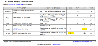
The desired configuration of the device is:
MODE: Level 1
SR: Level 1
DIAG: Level 1
IPROPI: 510 ohms in parallel with 100nF capacitor for 21 amp max current
ITRIP: Level 1
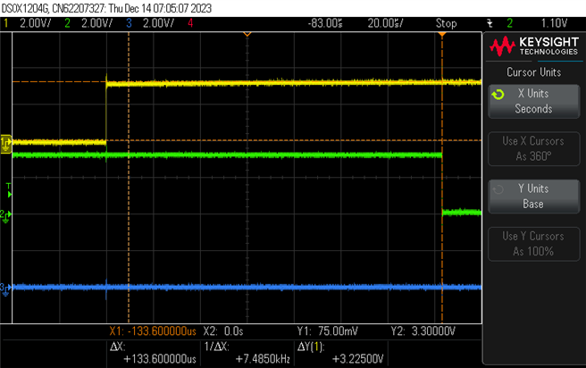
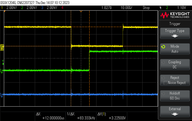
Scope output:

Circuit (Note: R21, R22, R23 are NOT placed on the circuit):