This thread has been locked.

If you have a related question, please click the "Ask a related question" button in the top right corner. The newly created question will be automatically linked to this question.

ULC1001-DRV290XEVM: ULC1001-DRV290XEVM

Part Number: ULC1001-DRV290XEVM
Other Parts Discussed in Thread: DRV2901, ULC1001

Hello,

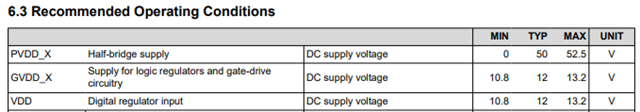
I checked the drv2901 datasheet and the evaluation board with ULC1001 and i found that you used a 35V boost converter in the EVM for PVDD.

Depending on the datasheet it supports between 12V to 48V and your power supply was 12V

why you didn't use the 12V directly?

what kind of effect to the performance and operation of the system the 12V to 48V input can have? is the piezo cleaning efficiency going to be reduced if 12V voltage is supplied in that case or another issue can happen? 

Also how much current will flow between the piezo's terminal?

Thanks

  • Hello,

    Thanks for reaching out. There are a few supplies for DRV2901, I included the recommended values from the datasheet below for easy reference. GVDD and VDD need to be around 12 V for operation of the device and the PVDD value is adjusted depending on the output voltage that is desired. In our EVM we found that the 35 V in combination with the output LC filter yielded good cleaning results on our cylindrical piezo lens cover system (LCS) prototype. Depending on the LCS being used, the PVDD value can be adjusted to increase or decrease the voltage being supplied to the load. 

    The current going to the LCS will be dependent of the LCS being used. The EVMs user guide has a few figures in section 4.4 System Cleaning that show the current and voltage for various cleaning modes with our LCS prototype.  

    Regards,
    Sydney Northcutt 

  • Hello,

    Thanks for your answer.

    So if i understand correctly the PVDD voltage will have an impact on the lens cleaning result? Is there any way to know the optimal voltage if we use different lens or require trial and error?

    As you mentioned the LC filter used in the EVM, could you provide us the inductor P/N used (L1+L2)? in the schematic it's just mentioned as 22uH but is there any other requirement for that inductor? (saturation current - DC current - core material). --- [by the way the BOM file is not provided for this project correct?]

    One last question: Any more detail about LC design for this chip for different PVDD? (the voltage range is quite big so any small change in values can cause some efficiency drop in the cleaning process)

    Thank you for your time and consideration.

  • Hello,

    Yes the PVDD value will have an impact on the cleaning result. When testing a new LCS with our EVM I recommend starting with a low PVDD or turning the amplitude down just so you avoid damaging your LCS, and then you can gradually increase this value until you get to a satisfactory result. 

    The part number for the 22uh inductor we use in our EVM is SRP7050TA-220M. Ultimately, the inductor choice will depend on the current being driven through the inductor. If the current is ~2Arms, then select an appropriate inductor to support this current level. The BOM for this project is not currently provided online.

    Different PVDD values can be used with the same LC filter on the EVM. In regards to just the LC filter, we are working to create a LC Filter guide that will have more information. 

    Regards,
    Sydney Northcutt