Hello Team,
I have 3 questions:
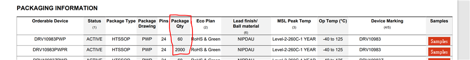
1. What is the difference between DRV10983PWP and DRV10983PWPR?
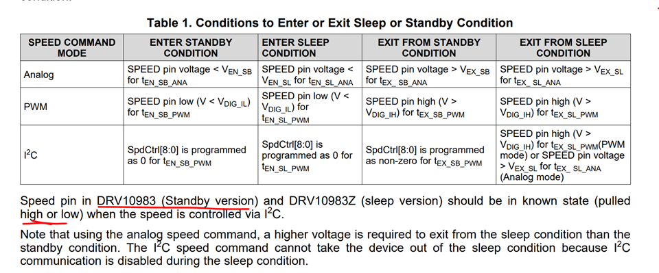
2. If no microcontroller is used, can all PINS 10 (SCL), 11 (SDA), 12 (FG), 13 (SPEED), and 14 (DIR), be left floating?
3. In the datasheet, it is mentioned "The following order of connections should be followed in order to avoid
hot-switching and floating ground, which may cause reliability issues: 1 - GND, 2 - VCC, 3 - PWM, 4 - FG", how and when should this order of connection be achieved?
Thanks in advance
Mohamed