


Hi Team,
The customer use the DRV8873HPWPR to control a DC brushed motor.
It's controlled in PWM mode with the following configuration:
MODE = 1, nSLEEP = 1, DISABLE = 0.
The current sampling points IPROPI1 and IPROPI2 are sampled separately during motor's forward and reverse. The voltage waveforms captured by the oscilloscope at IPROPI1 and IPROPI2 are as follows:
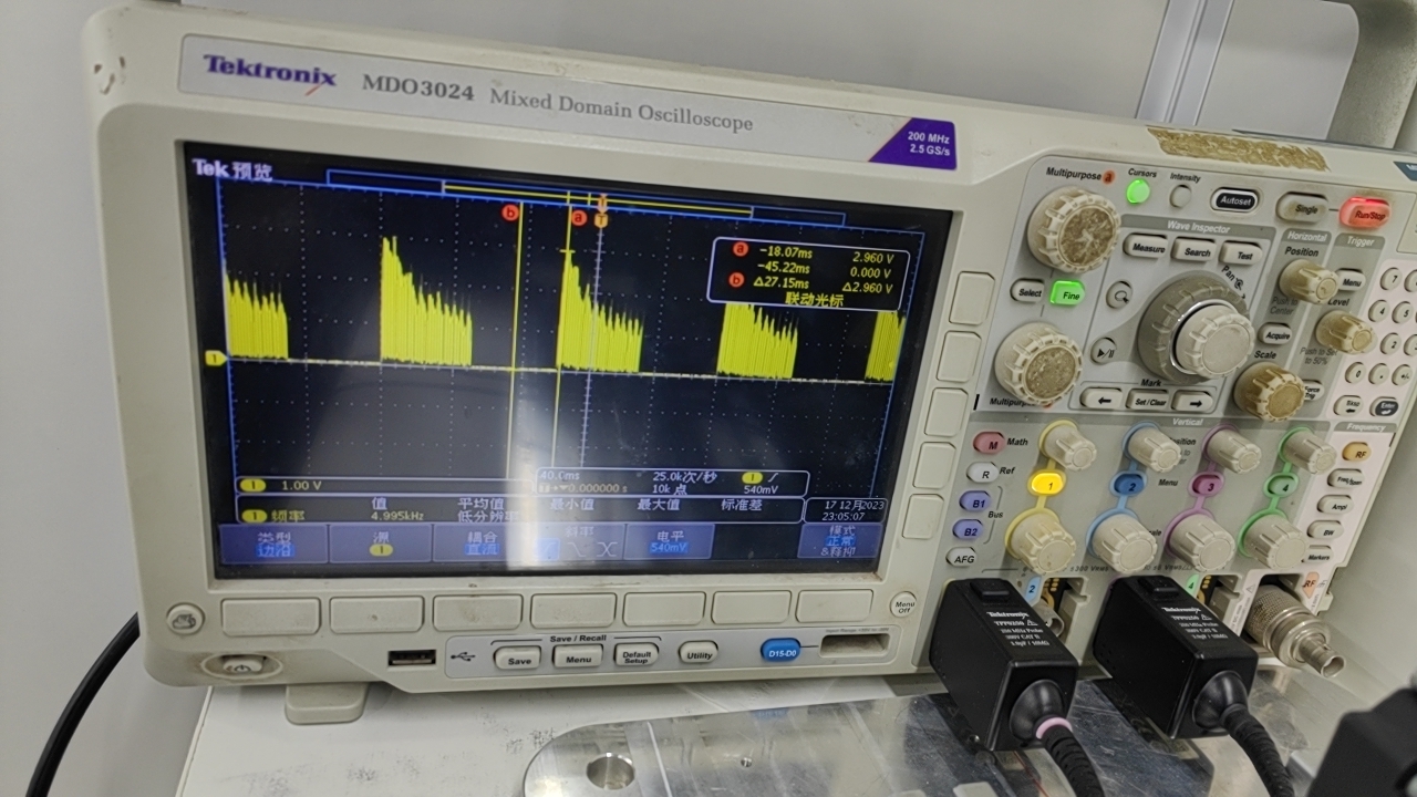
The waveform above with decreasing amplitude is PWM with a frequency of 20 KHz (the PWM driving the chip input is also 20 KHz).
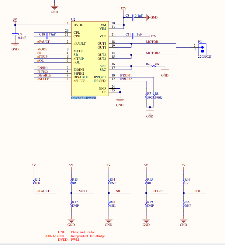
And the peripheral circuit is as follows:
Could you please help look into this case? Thanks.
Best Regards,
Cherry
